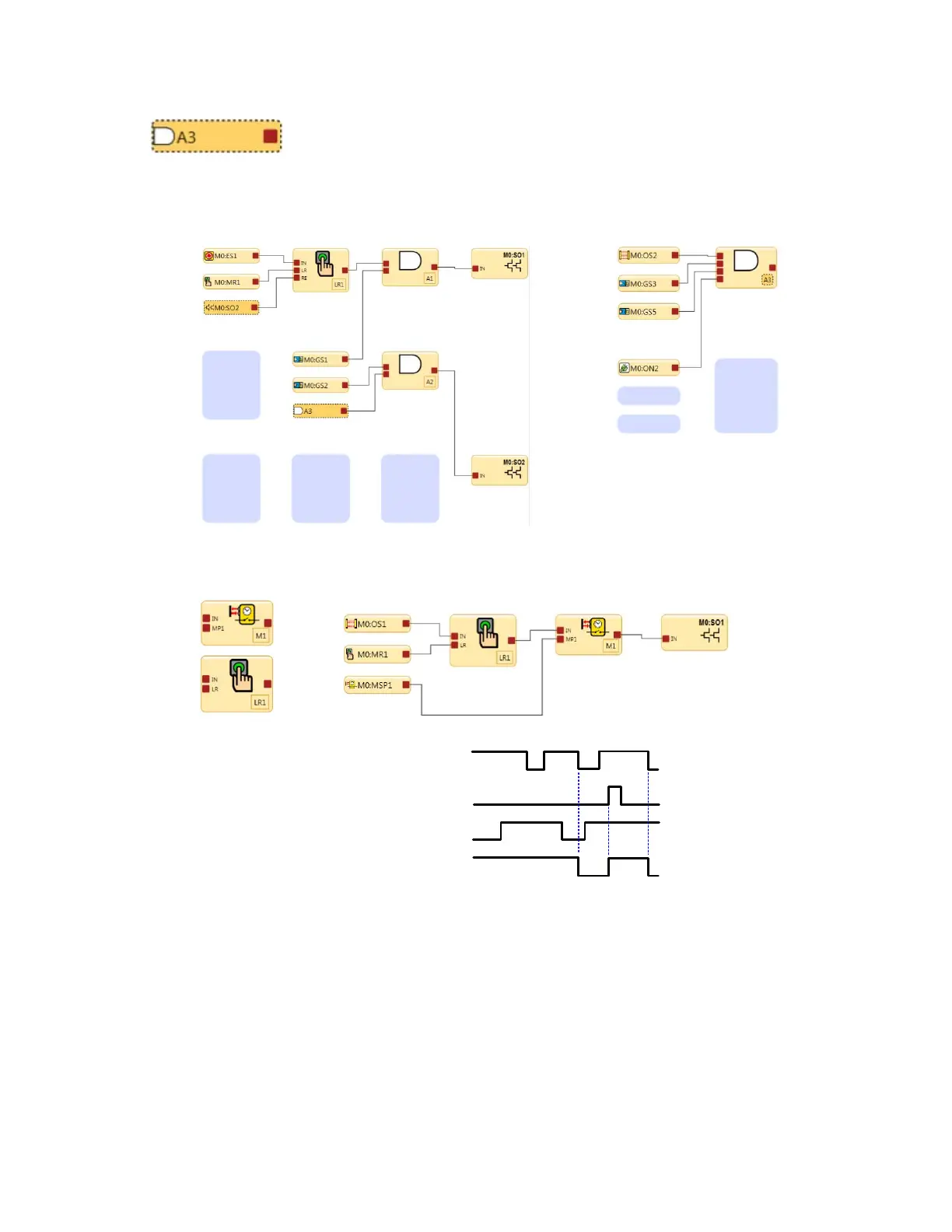
In the figure below, reference signal A3 is on page 1 of the function block diagram and the A3 AND
block is on page 2. The output node on the A3 AND block can also be used on page 2 for other
safety control logic.
Reference Signals
Reference signal A3 on page 1 AND logic block A3 on page 2
Figure 22. Latch Reset and Referenced Safety Output and AND block
When a safeguarding device OS1 transitions to the Stop state in a valid muting cycle, the latch
reset function block will not latch or require a reset signal.
If OS1 switches to the Stop state without the valid mute conditions, then the latch function block
LR1 and mute function block M1 will turn SO1 Off. A latch reset will be needed after OS1 changes
to the Run state.
M0:OS1
M0:MR1
M0:MSP1
M0:SO1
Latch Reset
Mute Function
Figure 23. Timing Diagram—Latch Reset Block and Muting Block
Manual Reset Input and Latch Reset Block
The Manual Reset input may be configured to perform any combination of the following (see Adding Inputs and Status
Outputs on page 19):
Reset of Safety Inputs
Sets the output of the Latch Reset Block(s) to a Run state from a Latched state when the IN node is in a Run state
XS/SC26-2 Safety Controller
30
 Loading...


