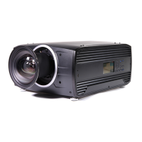
2. Lenses
2.4 Lens shift
General
Use the Remote control or the key pad on the Projector to adjust the lens shift mechanism.
The lenses can be shifted vertically and horizontally to facilitate prec ise image positioning in single and multiple projector systems.
The projector allows for hor izontal and vertical shift in both directions. Always place the pr ojector per pendicular to the screen, and
use the lens shift to align the picture.
If not possible to align the projector perpendicular to the s creen, due to environmemt of othe r, see chapt
er "Warp", page 42
Indexing
The position (index ) iris and shift (horizontal and vertical) c an be read out and set. T his allows for dynamic control of these functions
from an external control system.
Indexing of zoom and focus a re supported on lens ID EN6x (EN61) range
2.5 Locking the lens position
About
The m echa nically lens lock is particularly important in moving platform applications in order to avoid that the lens comes out of
position during operation. See the procedure explained below to perform this.
WARNING: This procedure must be performed ONLY by Barco trained service personnel. Opening the unit
may cause a risk o f e lectrical sho ck, and exposure to high intensity laser beam.
See also the Safety chapter in this manual.
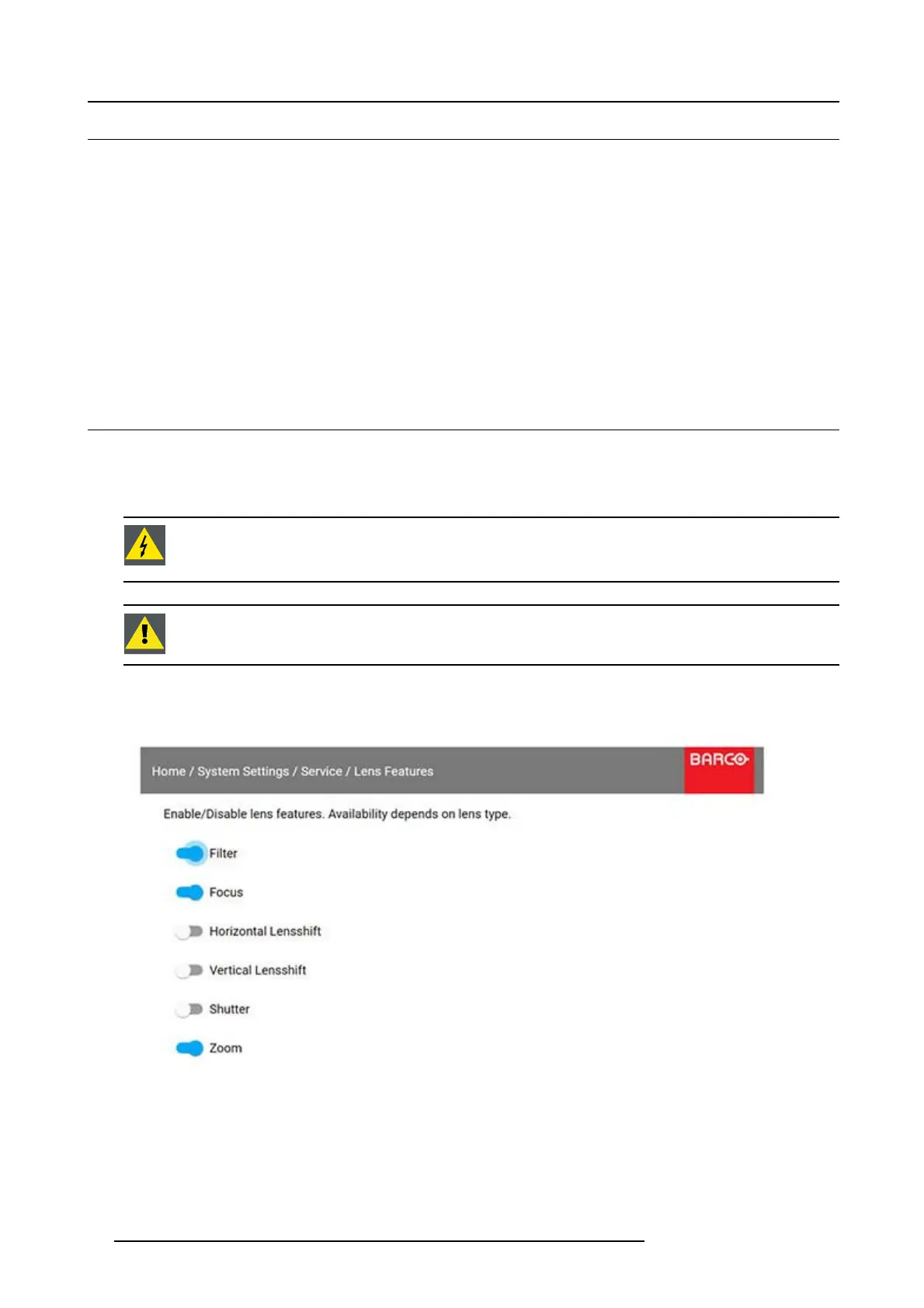
CAUTION: It is of great importance to disable the Lens Shift function when the mech anically lens lock is
performed. If no t, the shift mechanism will be p ossible destructed if lens sh ift accidentally is performed when
the mechanism is mechanically locked.
1. Adjust the lens shift b y the remote or keypad, to the desired position.
2. Disable the Lens Shift function by entering the menu Home/System Settings/Service/Lens Features, and disable the Horizontal
and Vertica l lens shift by toggling the s w itches in the m enu.
Image 2-5
3. Remov e the lens from the Projector.
4. Unscrew the 14 screws indicated in the illustration below.
16
601–0442 BALDER 13/09/2017