3. Physical Installation
Parameter Value
Thread size M12
Length 18mm max 18mm max
Where possible, the projector lens mu st be positioned exactly perpen dicular to the center of the sc reen. Use
the projector offset (lens shift), rather than phys ical angling, to correct any o ff-center positioning.
CAUTION: The position and physical securing of the projector must be su fficient to preven t it from accidental
or involuntary movem ent. Proper securing of the projector is the responsibility o f the in staller and user.
CAUTION: Always use a Rigging Frame when the projector shall be mounted in other ways than on the feet,
on a flat surface.
The threaded hole in the lower back end of the projector is NOT suitable for lifting or other heavy operations.
Only for adjustment purposes.
Installation and use of the Rigging Frame are d escribed in document R5906768 Multifunctional Frame — In-
stallation Manual.
Mounting on a flat surface
1. Position the projector at the d esired location.
2. Power up t he projector.
3. Go to Main Menu / Test Patterns and select an internal hatch pattern to display on the screen.
4. Adjust the projector legs until the p rojected hatch pattern is a level and perfect rectangle.
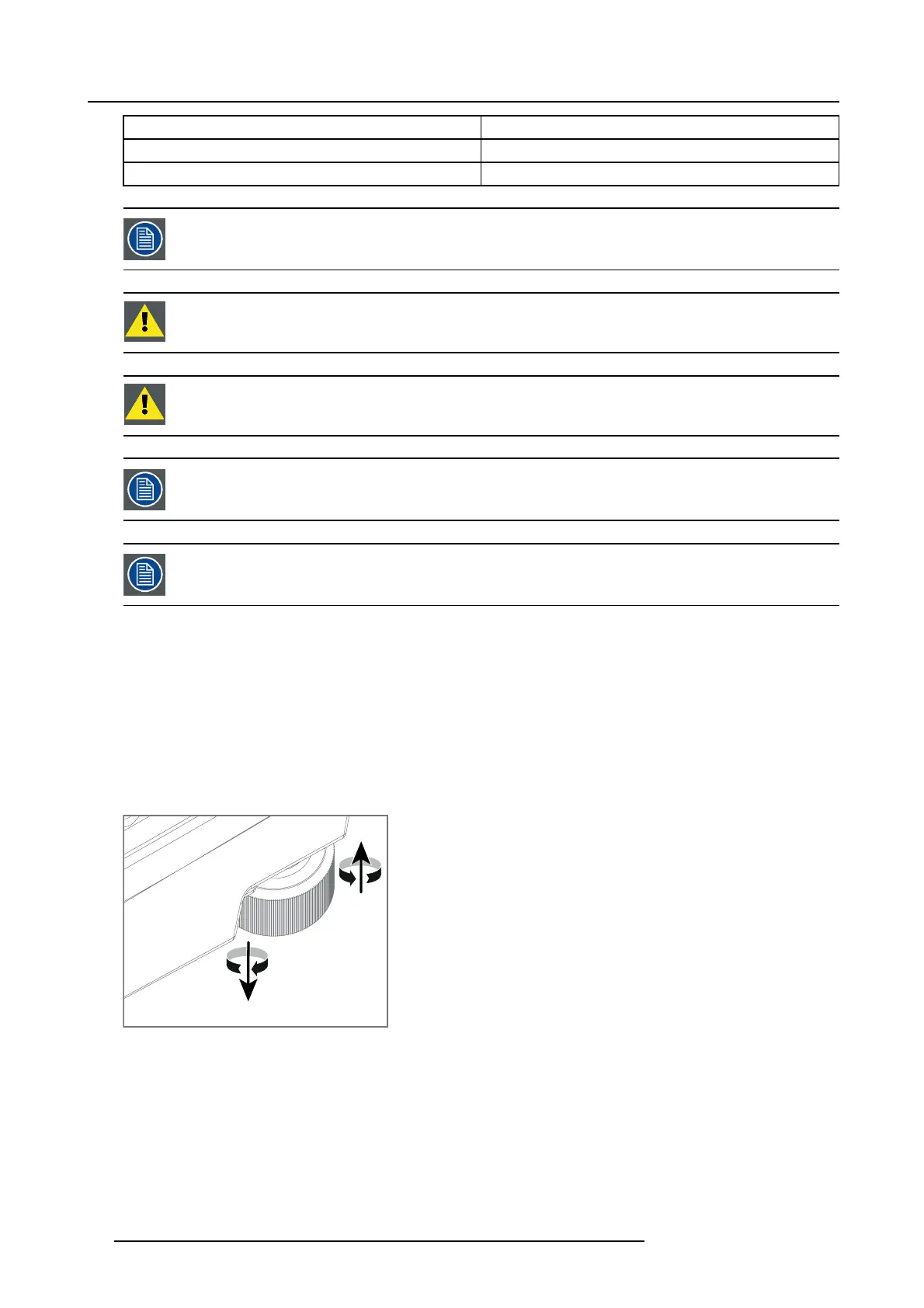
Adjustable feet
Twisting the adjustable feet in either direction, left or right, allows you to fine-a djust the projector position for precise vertical m e-
chanical alignment.
Raise
Lower
Image 3-2
Mounting to a ceiling
1. Install the projector in to an approved ri
gging frame.
2. Install the rigging frame to the desired location.
3. Power up t he projector.
4. Go to Main Me nu / Installation / Orientation a nd select the correct o rientation for yo ur setup.
5. Go to Main Menu / Test Patterns and select an internal hatch pattern to display on the screen.
6. Adjust the position (height and angle) of the rigging frame until the projected hatch pattern is a level and perfect rectangle.
22
601–0442 BALDER 13/09/2017