2. Lenses
5. Carefully remove the front cove r
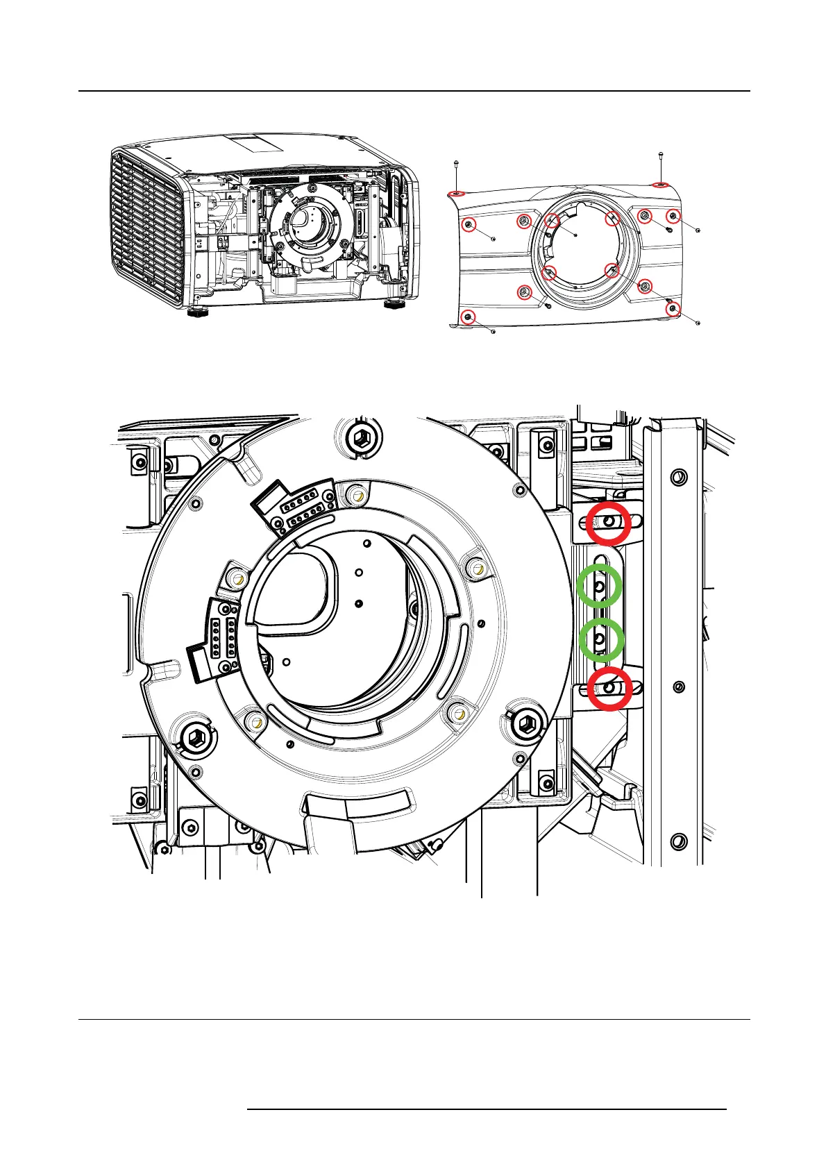
Image 2-6
6. Insert M 4 pan head screws (not supplied) with a maximum length of 15mm in the threaded holes, indicated by the red and green
circles in the illustration below. Tighten the screws with a sufficient torque. T he g reen circles indicate the lock for the vertical shift,
and the red circles indicate the lock for the horizontal shift. All four lock ing positions mus t be used to achieve a sufficient locking.
Image 2-7
7. Reinstall the front cover.
8. Reinstall the Projector lens.
2.6 Adjust zoom and focus
General
Zoom controls the size of the projected image.
601–0442 BALDER 13/09/2017
17