7. Input & communication unit
7.3 Communication ports of the DP-1500 projector
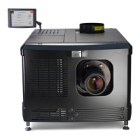
Location of the communication ports
A B C
D E F G
Image 7-3
A Communication port for the touch panel.
B RS 232 input port.
C General purpose input/output p ort (GPIO).
D (Future expansion).
E +12 VDC output port (max imum 2 ampere).
F Master USB port type A.
G Four Ethernet ports RJ45.
TOUCH PANEL
This female D B-9 connector allows you to use a standard s erial cable up to 10 meter to connect t he touch panel interface with the
projector. Note that the RS232 protocol is used on this connection.
RS232 IN
This female DP -9 connector is only used for service purpos es. Do not use this c onnector to comm unicate with the projector.
RS232
An Electronic Industries Association (EIA) serial digital interface standard specifying the characteristics of t he commu-
nication path between two devices using either D-SUB 9 pins or D-SUB 25 pins connectors. This s tandard is used for
relatively short-range communications and do es no t specify balanced control lines. R S-232 is a serial control standard
with a s et number of cond uctors, data rate, word length and type of connector to b e use d. The standard specifies com-
ponent connection standards with regard to c omputer interface. It is also called RS-232 -C, which is the third version
of the RS -232 standard, and is functionally identical to the CCITT V.24 standard. Logical ’0’ is > + 3V, Logical ’1’ is < -
3V. The ran ge between -3V and +3V is the transition zone.
GENERAL PURPOSE IN/OUT
This 37 pins connector can be used to send or receive trigger signals from other devices. T hese input/output pins can be pro-
grammed by m acros created on the Comm unicator touch panel. See user ’s guide of the Touch panel, section Macro editor, for more
information about this functionality. Note that the G eneral Purpose Inputs accept 24 volt maximum.
DC OUT
This fuse protected m ono jack socket provides a +12 V D C voltage and m aximum 1,5 ampere. T he DC O UT socket has gr ound
(GND) in the middle and +12V on external pin. This is opposite of the Bar co Touch P anel Comm unicator power connection. So, a
cross c able is need ed when connecting the DC O UT directly to the Touch Panel.
USB port
The comm unication interface is equipped with a ma ster USB port, type “A” connector (F). This USB port is for future expansion.
10/100 BASE - T
The D P-1500 projector can be connected to a LAN (local area network) using one of the Ethernet p orts (G) on the communication
interface. Once connected to the LA N, users a re capable of accessing the projector from any location, inside or outside (if allowed)
their company network using the Com municator software. This s oftware locates the pr ojector on the network in c ase there is a DHCP
server or the user can insert the correct IP-address of the projector to access the pr ojector. O nce accessed, it is possible to check
and manipulate all the projector settings. Remote diagnostics, control and monitoring of the projector can then become a daily and
very simple ope ration. The network conn ectivity permits to detect potential errors a nd c onsequently improve the time to servicing.
66
R59770091 DP-1500 06/01/2009
 Loading...