47R5912128 /03 SP4K-B
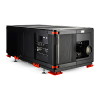
Image 4–8 Y configuration
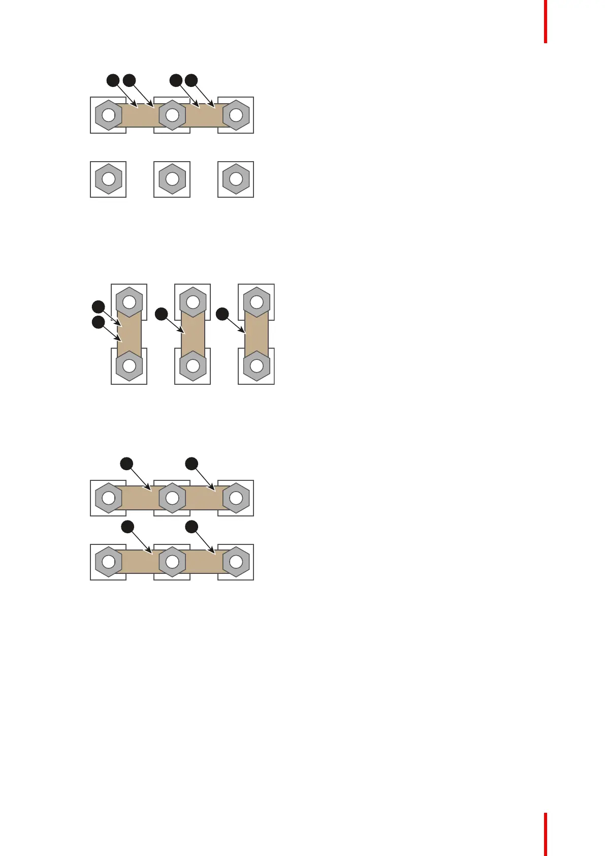
2. Δ configuration: Connect the upper pins with the bottom pins as illustrated. Place two links between
pin W2 and U1 (A and B).
Image 4–9 Δ configuration
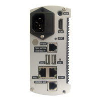
3. Mono phase configuration: Spread the four links over the six pins as illustrated. Make sure both the
upper and lower pins are connected with each other.
Image 4–10 Mono phase configuration
4. Turn a nut on each pin and secure with a torque wrench set to 3.5 Nm.
Physical installation projector