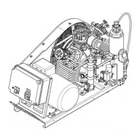
3.1.2 Function schematic
The function schematic shows the route of the air through the compressor unit.
The type and scope of the components depend on the unit configuration, the func-
tional principle and arrangement of the components remain the same, however.
Fig. 6 Function schematic
1 Intake filter 6 Condensate drain valve (option) 11 Changeover device (option)
2 Compressor block 7 Cartridge filter with integrated fi-
nal separator
12 Filling valve, PN300
3 Cooler 8 Condensate drain valve, final
separator (option)
13 Filling valve, PN200
4 Safety valve 9 Pressure maintaining valve 14 Condensate vessel (option)
5 Intermediate separator 10 Safety valve, final pressure
OPERATING MANUAL Product description | 3
28.08.2019
A_002_en
33/150
 Loading...