Commissioning
Instruction handbook CANopen slave BM4-O-CAN-03
Document no. 5.02014.06
33
of 68
6
6.5 Description/check of operation and display elements
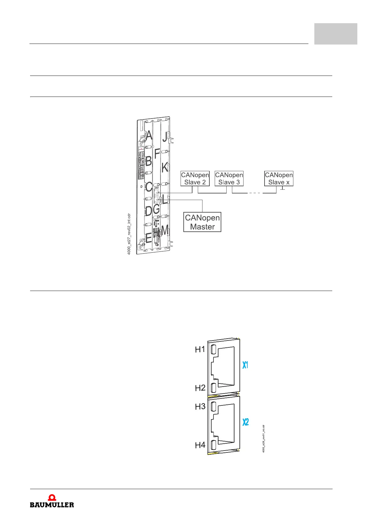
6.5.1 Configuration example
Figure 9: b maXX with CANopen slave for b maXX PLC on slot G and b maXX PLC on slot H
6.5.2 LEDs
The RJ45 connectors X1 and X2 are equipped with 2 LEDs (green and red) each. The
LEDs are named H1 to H4. The LEDs display the operation state of the option module
CANopen slave.
LED green
LED red
LED green
LED red
Figure 10: LEDs on option module CANopen slave
 Loading...