59
926.116.5 - en
INSTRUCTIONS FOR FITTERS
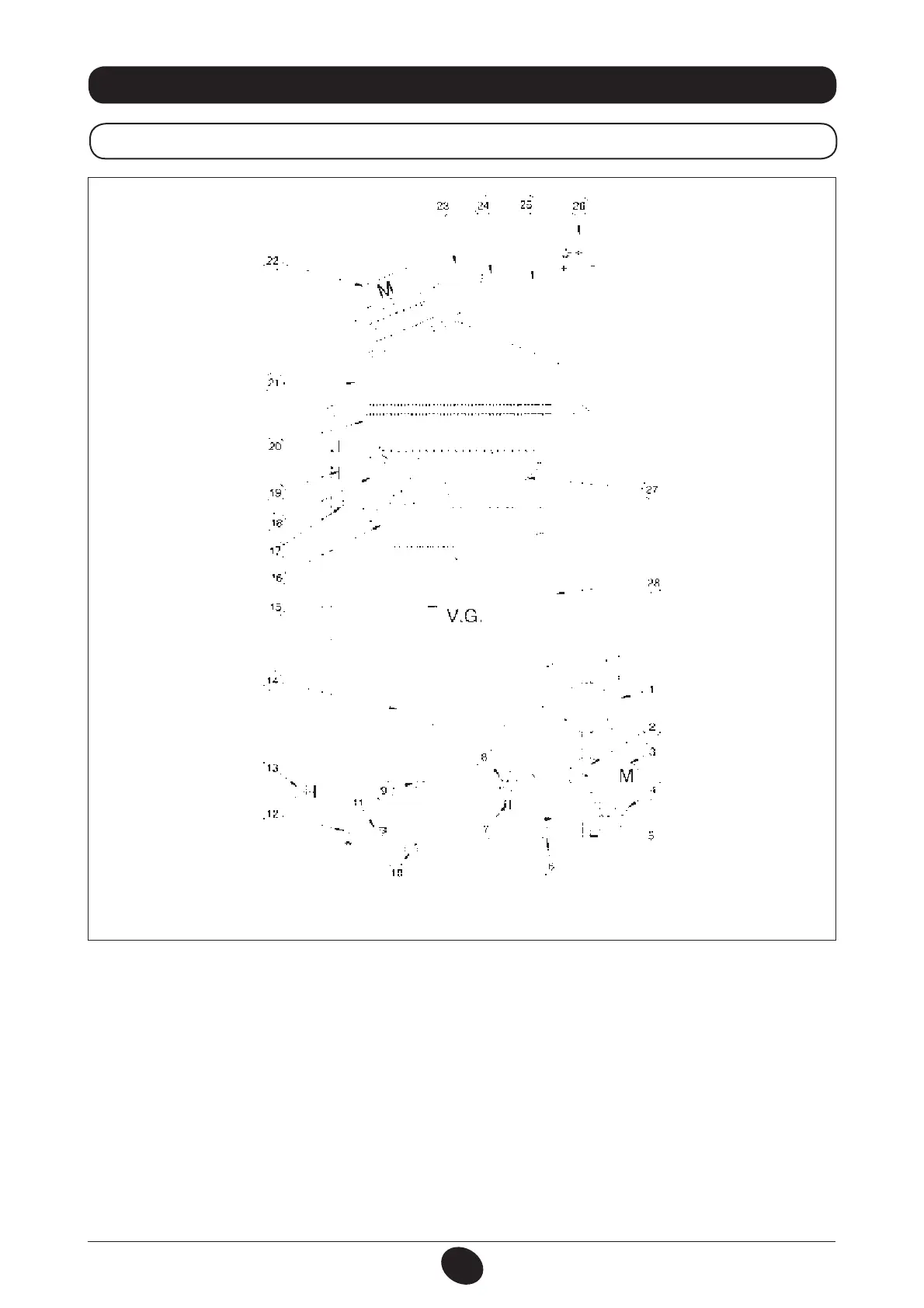
32. FUNCTIONAL CIRCUIT DIAGRAM
24 F
Legend:
1 Pump and air separator
2 Three-way valve
3 Three-way valve motor
4 Pressure gauge
5 Heating circuit extractable lter
6 Boiler lling tap
7 Cold water extractable lter
8 DHW priority sensor
9 NTC domestic hot water sensor
10 Check valve on automatic by-pass
11 Water pressure switch
12 Boiler drain tap
13 Safety valve
14 Water-water plate heat exchanger
15 Gas valve
16 Gas train with injectors
17 Central heating NTC sensor
18 Ignition / ame detection electrode
19 Safety thermostat
20 Water-fumes exchanger
21 Fumes conveyor
22 Fan
23 Venturi tube
24 Positive pressure point
25 Negative pressure point
26 Air pressure switch
27 Burner
28 Expansion vessel
Figure 17
Heating
delivery
DHW
outlet
Gas DHW
inlet
Heating
return
CG_2082 / 1001_1802