49
926.116.5 - en
INSTRUCTIONS FOR FITTERS
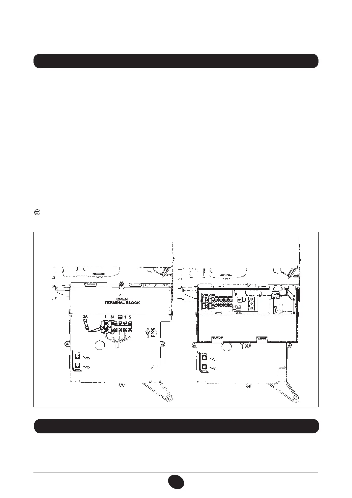
Figure 9
0712_1208 / CG_2008
IMPORTANT:
if tting a single ue duct, make sure it is adequately insulated (e.g.: with glass wool) wherever the duct
passes through building walls. For detailed installation instructions, consult the technical data provided with the accesso-
ries.
17. ELECTRICAL CONNECTIONS
This machine is only electrically safe if it is correctly connected to an efcient earth system in compliance with current
safety regulations.
Connect the boiler to a 230V single-phase earthed power supply using the supplied three-pin cable, observing correct
LIVE-NEUTRAL polarity.
Use a double-pole switch with a contact separation of at least 3 mm.
When replacing the power supply cable, t a harmonised HAR H05 VV-F’ 3x0.75mm2 cable with a maximum diameter
of 8 mm.
…Access to the power supply terminal block
r EJTDPOOFDUUIFCPJMFSGSPNUIFNBJOTQPXFSTVQQMZVTJOHUIFUXPQPMFTXJUDI
r SFNPWFUIFUXPTDSFXTàYJOHUIFDPOUSPMQBOFMUPUIFCPJMFS
r SPUBUFUIFDPOUSPMQBOFM
r SFNPWFUIFDPWFSBOEBDDFTTUIFXJSJOHBSFBàHVSF
The 2A fast-blowing fuse is incorporated in the power supply terminal block (to check and/or replace the fuse, pull out
the black fuse carrier).
IMPORTANT: respect polarity L (LIVE) - N (NEUTRAL).
(L) = Live (brown)
(N) = Neutral (blue)
= Earth (yellow-green)
(1) (2) = Contact for ambient thermostat
18. CONNECTING THE ROOM THERMOSTAT
r BDDFTTUIFQPXFSTVQQMZUFSNJOBMCMPDLàHVSFBTEFTDSJCFEJOUIFQSFWJPVTTFDUJPO
r SFNPWFUIFKVNQFSPOUFSNJOBMTBOE
r UISFBEUIFUXPXJSFDBCMFUISPVHIUIFHSPNNFUBOEDPOOFDUJUUPUIFTFUXPUFSNJOBMT