50
926.116.5 - en
INSTRUCTIONS FOR FITTERS
The authorised Technical Assistance Service can convert this boiler to natural gas (G20) or liquid gas (G31).
19. GAS CONVERSION
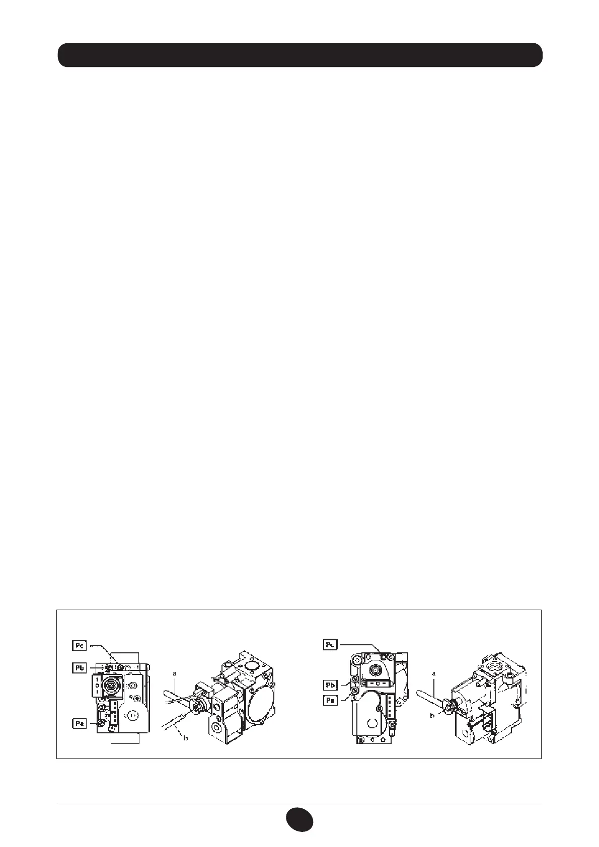
The procedure for calibrating the pressure regulator varies slightly according to the type of gas valve tted (HONEYWELL
or SIT, see gure 10).
Carry out the following operations:
A) replace the main burner nozzles;
B) change the modulator voltage
C) new max. and min. calibration of the pressure regulator.
A) Replace the burner injectors
r DBSFGVMMZQVMMUIFNBJOCVSOFSPGGJUTTFBU
r SFQMBDFUIFNBJOCVSOFSJOKFDUPSTNBLJOHTVSFUPGVMMZUJHIUFOUIFNUPQSFWFOUHBTMFBLT*OKFDUPSEJBNFUFSTBSFTQFDJàFE
in table 2.
B) Change the modulator voltage
r TFUQBSBNFUFSF02 according to the gas used, as described in section 21;
C) Calibrate the pressure regulator
r DPOOFDUUIFQPTJUJWF QSFTTVSF UFTUQPJOUPG BEJGGFSFOUJBM QSFTTVSF HBVHFQPTTJCMZXBUFSPQFSBUFEUPUIF HBTWBMWF
pressure test point (Pb) (Figure 10). Only for models with sealed chambers, connect the negative pressure test point
of the pressure gauge to a “T” tting in order to join the boiler adjustment outlet, the gas valve adjustment outlet (Pc)
and the pressure gauge. (The same measurement can be made by connecting the pressure gauge to the pressure test
point (Pb) after removing the front panel of the sealed chamber). Measuring burner pressure using methods other than
those described could lead to incorrect results as the low pressure created by the fan in the sealed chamber would not
be taken into account.
C1) Adjustment to nominal heat output:
r PQFOUIFHBTUBQBOETXJUDIUIFCPJMFSUPUIF8JOUFSNPEF
r PQFOBIPUXBUFSUBQUIBUDBOQSPWJEFBáPXSBUFPGBUMFBTU10 litres a minute or make sure there is maximum heat
demand;
r SFNPWFUIFNPEVMBUPSDPWFS
r BEKVTUUIFCSBTTTDSFXBVOUJMUIFQSFTTVSFWBMVFTTIPXOJOUBCMFBSFPCUBJOFE
r NBLFTVSFUIBUUIFEZOBNJDJOMFUQSFTTVSFPGUIFCPJMFSNFBTVSFEBUUIFHBTWBMWFQSFTTVSFUFTUQPJOU1B'JHVSF
is correct (37 mbar for propane or 20 mbar for natural gas).
C2) Adjustment to reduced heat output:
r EJTDPOOFDUUIFNPEVMBUPSQPXFSDBCMFBOEVOTDSFXUIFTDSFXb) until a pressure value corresponding to reduced heat
output is achieved (see tab. 1);
r SFDPOOFDUUIFXJSF
r NPVOUUIFNPEVMBUPSDPWFSBOETFBM
C3) Final checks
r BUUBDIUIFBEEJUJPOBMQMBUFTVQQMJFEXJUIUIFUSBOTGPSNFSTQFDJGZJOHUIFUZQFPGHBTBOEUIFDBMJCSBUJPOQFSGPSNFE
Figure 10
SIT valve - mod. SIGMA 845 Honeywell valve - mod. VK 4105 M
0904_0701