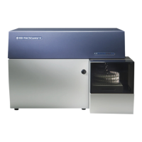
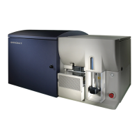
24 BD FACSCanto Flow Cytometer Reference Manual
Electronics
The electronics system converts optical signals to electronic signals and digitizes
them for computer analysis. The photodiode and PMTs generate signals
proportional to the amount of light they detect. The cytometer’s onboard
electronics amplifies and then converts the signals from continuous voltage
values (analog) into discrete values (digital). Upon amplification and digital
conversion, fluorescent light signals from consistently prepared and stained
particles characteristically fall into certain channels, thus allowing analysis.
On the BD FACSCanto, electronic system components consist of power controls
and connectors along with processing boards in the card cage. This section
describes only the user-accessible power panel. For more information, see
Electronics System on page 120.
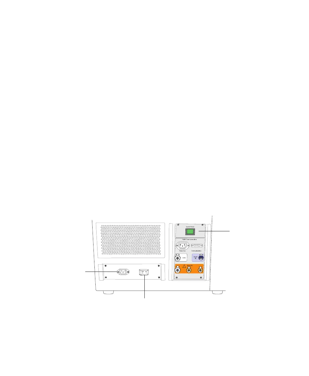
Power Panel
Power to the cytometer, lasers, and fluidics cart is supplied by a power cord from
the cytometer plugged directly into a standard electrical outlet. BD recommends
using an uninterrupted power supply (UPS) unit to maintain cytometer power
during a power outage. The system power button turns on the cytometer and
fluidics cart, and powers the lasers (Figure 1-4).
Figure 1-4 Flow cytometer power panel
The system circuit breaker is located next to the AC power cord. The breaker will
need to be reset if there is a power surge in the laboratory.
system circuit breaker
system power
button
system AC power
cord plugs in here