31
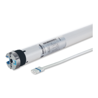
Roller shutter
Drives
Information
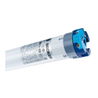
E03 drives with electronic limit switching
detect and program both limit positions
automatically. If no stops exist, limit switch
points are programmed.
In order for the drive to detect the upper
limit position automatically, a defined
stop must be present (angled strip or
mechanical stop).
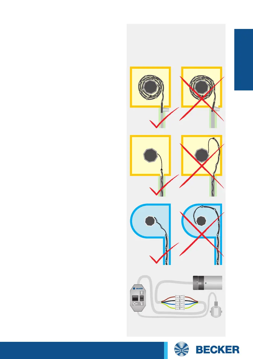
Installation with springs
No more than one roller shutter slat
should jut out over the intake guide. In
the lower limit position, the springs must
act against the tube’s rotary motion. The
springs should be mounted 30 cm apart
from one another.
Installation with anti-lifting devices
The anti-lifting device must be securely
engaged and be pressing the roller shutter
onto the window sill.
The limit positions can be set using any
operator control.
Limit positions are deleted using the
programming unit.
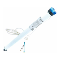
Connect the wires in the connecting
cable of the drive to the wires of the
same colour in the programming unit.