SectionVI BEECHCRAFT Bonanza
V35. V35A & V35B thru D-9947
Wtand Bal/Equip List
Measurements are taken, with the airplane level on
the scales, from the reference (a plumb bob dropped
from the center of either main jack point) to the axle
center line of the main gear and then to the nose
wheel axle center line. The main wheel axle center
line is best located by stretching a string across from
one main wheel to the other. All measurements are to
be taken with the tape level with the hangar floor and
parallel to the fuselage center line. The locations of the
wheel reactions will be approximately at Fuselage
Station 96.7 for main wheels and Fuselage Station
12.7 for the nose wheel.
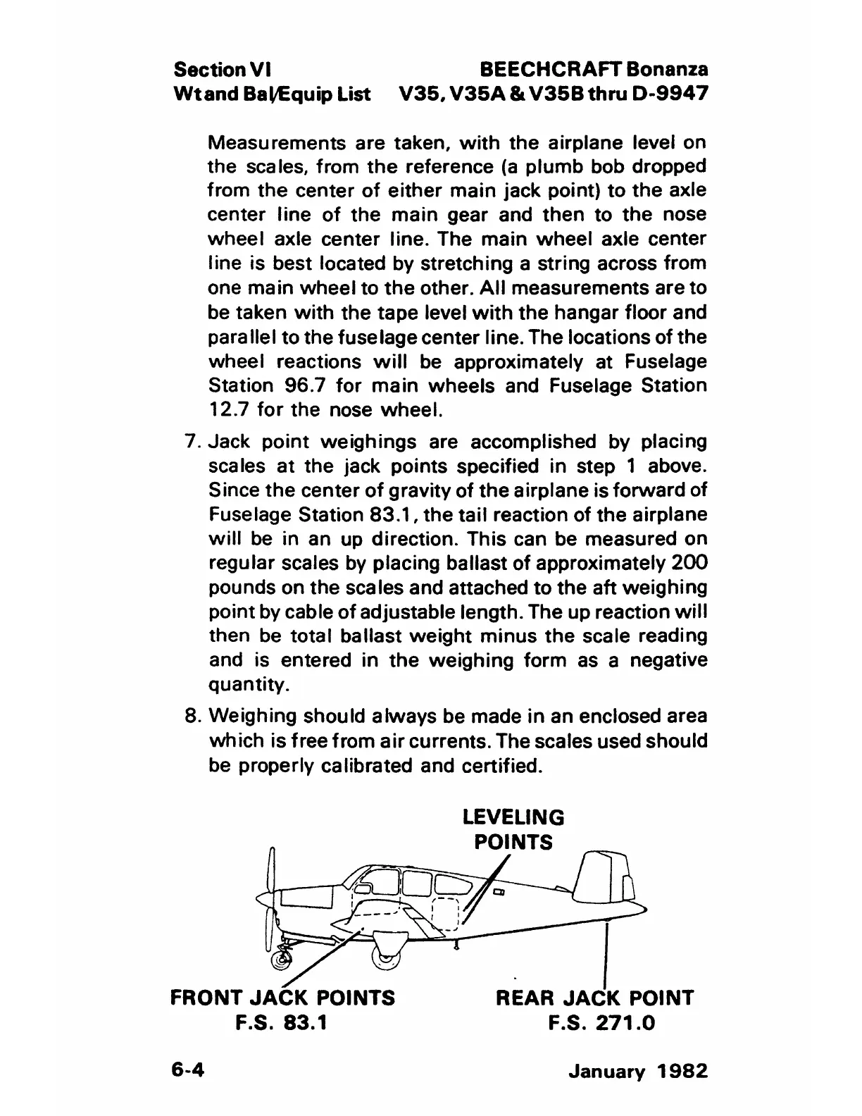
7. Jack point weighings are accomplished by placing
scales at the jack points specified in step 1 above.
Since the center of gravity of the airplane is forward of
Fuselage Station 83.1, the tail reaction of the airplane
will be in an up direction. This can be measured on
regular scales by placing ballast of approximately 200
pounds on the scales and attached to the aft weighing
point by cable of adjustable length. The up reaction will
then be total ballast weight minus the scale reading
and is entered in the weighing form as a negative
quantity.
8. Weighing should always be made in an enclosed area
which is free from air currents. The scales used should
be properly calibrated and certified.
FRONT JACK POINTS
F.S. 83.1
6-4
LEVELING
POINTS
REAR JACK POINT
F.S. 271.0
January 1982