QUICKFIRE® WRAP AROUND
28 Belanger, Inc. * 1001 Doheny Ct. * Northville, MI 48167 * Ph (248) 349-7010 * Fax (248) 380-9681 1MANUL825
Installation
Securing the Head Assembly to the Boom: Electric
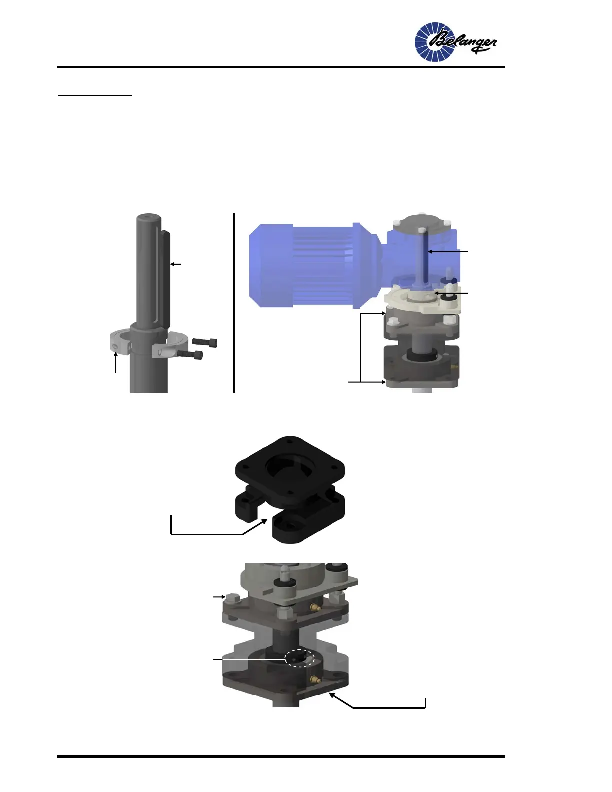
Installing Electric Drive Shaft Components
The shaft is held in place using a steel key, two setscrews in each of the two bearings and a split-locking collar.
There is a groove in the shaft to accommodate the locking collar. The setscrews in the bearings are shown in a
close-up image at the bottom of this page. See the images below to understand how the complete assembly goes
together then follow the instructions on the next page.
2) Locate the Bearing Mount shown below and notice the slotted opening. That is to allow access to
the bearings setscrews and grease fitting. Be sure to align these components in a way that they
can be accessed.
3) Loosen both setscrews in each of the shaft bearings.
4) Locate the two side-wheel shafts. Locate the accessory box and separate its contents.
Locking Collar
Bearing
Locking Collar
Key
Be sure to align bearings
setscrews and the grease fitting
in a way that they can be
accessed
Lower bearing set
screw (typical)
Key
Bearing Mount
Be sure to align bearings
setscrews and the grease fitting
in a way that they can be
accessed
You may need to loosen these
four bolts in order to slide the
shaft up through the bearings.
If that is indeed necessary, be
sure to retighten them once
the shaft is in place