Connection
23
NGRM7xx_D00292_07_M_XXEN/02.2022
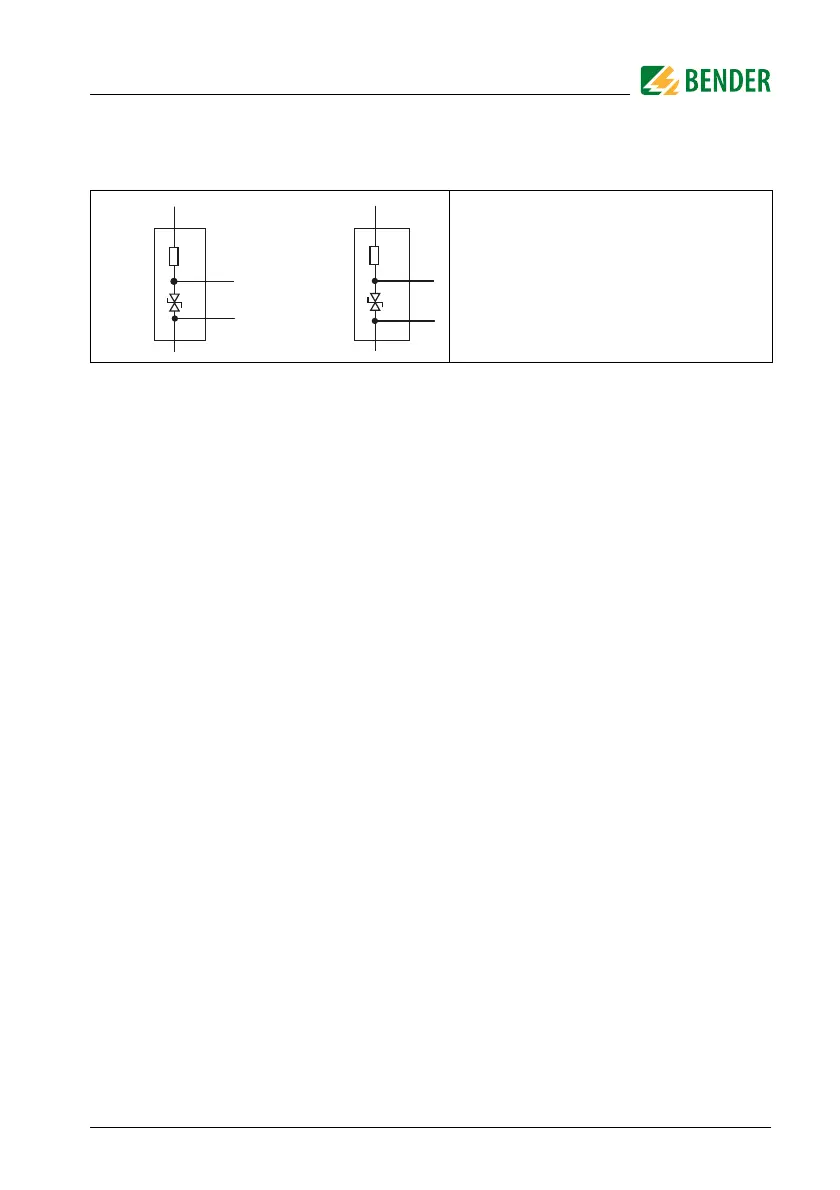
5.2 Connection descriptions of CD-series coupling device
N Connection to star point
G1, R
S
Connection to R
S
of the NGRM7…
G, E Connection to E of the NGRM7…
and to the protective earth con-
ductor of the installation (PE)
R
s
E
N
CD1000-2
CD14400
CD25000
PE
G1
PE
N
CD1000
CD5000
G