User interface FP200-NGRM
33
NGRM7xx_D00292_07_M_XXEN/02.2022
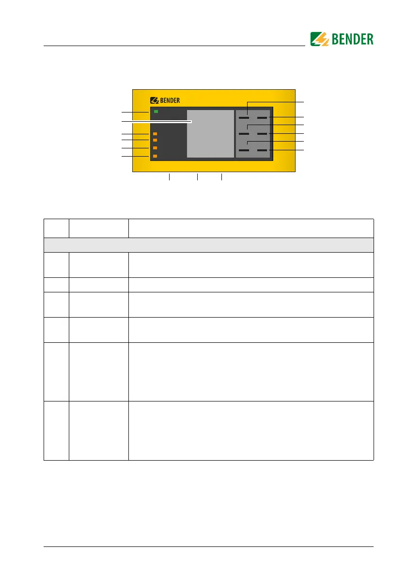
6. User interface FP200-NGRM
Legend, FP200-NGRM
No. Description Explanation
Display elements
1 ON
Operation LED, green;
on when power supply is available
2 The LC display shows device and measurement information.
3 SERVICE
The LED is on when there is either a device fault or a connection
fault, and when the device is in maintenance mode.
4 TRIPPED
The LED is on when the trip relay has been tripped due to an NGR
fault, a ground fault or a device error.
5 NGR FAULT
The LED flashes in case of a prewarning: NGR fault detected, NGR-
fault relay has tripped, trip relay has not tripped yet (t
NGR trip
elapses).
The LED is on when an NGR fault has been detected. Trip relay and
NGR-fault relay have tripped.
6
GROUND
FAU LT
The LED flashes in case of a prewarning: ground fault detected,
ground-fault relay has tripped, trip relay has not tripped yet
(t
GF trip
elapses).
The LED is on: ground fault detected, trip relay has tripped, instal-
lation has not been shut down yet.
SERVICE
TRIPPED
NGR FAULT
GROUND FAULT
ON
MENU
RESET
DATAINFO
*
<
<
<
<
OK
ESC
TEST
FP200