Connection
32
NGRM7xx_D00292_07_M_XXEN/02.2022
5.6.3 X1: Analogue output
Either NGR current I
NGR
or NGR resistance R
NGR
can be assigned to the analogue out-
put. A voltage or current signal proportional to the measured value is applied to the
output.
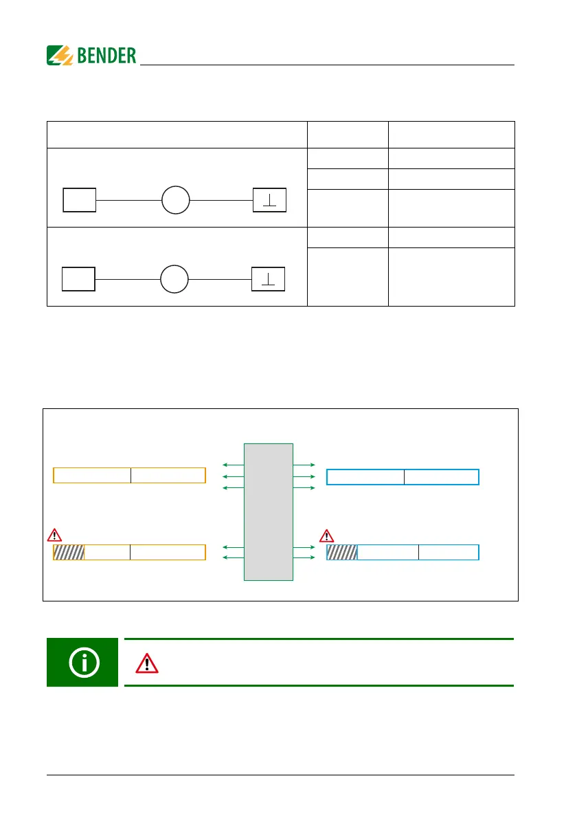
The following overview shows how the output signals (A or V) are proportional to the
measured values ( or A):
Fig. 5.6: Assignment of measured value to output signal
l
Analogue output Mode Permissible load
Current output 0…20 mA ≤ 600
4…20 mA ≤ 600
0…400 µA ≤ 4 k
Voltage output 0… 10 V ≥ 1 k
2… 10 V ≥ 1 k
In "4…20 mA" and "2…10 V"
mode an output signal of 0 mA or 0 V
indicates a
wiring error of the analogue interface
.
M
+
A
X1 X1
0
0
10 mA 20 mA
100 % ≥ 200 % R
NGR
200 μA
5 V
400 μA
10 V
0
0
10 mA 20 mA
50 % ≥ 100 % I
NGR
200 μA
5 V
400 μA
10 V
4…20 mA
2…10 V
0…400 µA
0…20 mA
0…10 V
Function: I
NGR
Function: R
NGR
Mode
Analogue output
20 mA
100 % ≥ 200 % R
NGR
≤ 40 %
10 mA4 mA
10 V5 V 2 V
20 mA
≥ 100 % I
NGR
0 %
12 mA4 mA
10 V6 V2 V
50 %
0
0