Connection
29
NGRM7xx_D00292_07_M_XXEN/02.2022
5.5 Connection of relays
(ground-fault, NGR and trip relay)
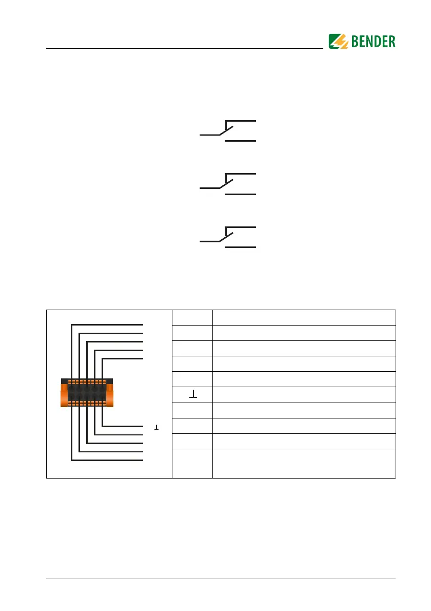
Fig. 5.5: Connection of relays
5.6 Connection to the X1 interface
Tab. 5.2: Pin assignment X1 interface
I1 Digital 1 (configurable: pulser, NGR method)
I2 Reset IN
I3 Test IN
A Modbus RTU (A)
B Modbus RTU (B)
Common
M+ Analogue output
Q2 Open Collector: Pulser OUT
Q1 Open Collector: Device health
+
Output for supply of external relays
(+24 V, max. 100 mA)
Ground-fault relay
NGR-fault relay
Trip relay