User interface FP200-NGRM
35
NGRM7xx_D00292_07_M_XXEN/02.2022
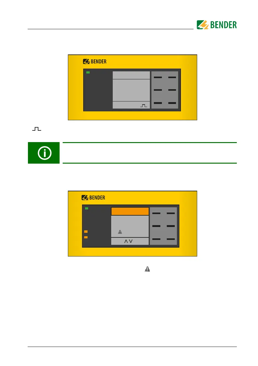
6.1 Standard display
The pulse symbol in the lower part of the display indicates that the resistance
of the R
NGR
is actively measured.
6.2 Fault indication (active)
An active fault is indicated on the display with a while the upper part of the display
turns orange and displays the fault message. Depending on the fault type, the GROUND
FAULT, NGR FAULT, TRIPPED or SERVICE LEDs will be on. If several fault messages
appear, navigate through the faults using the and buttons.
Return from any (sub)menu to the standard display by pressing and
holding ESC for more than 2 s.
SERVICE
TRIPPED
NGR FAULT
GROUND FAULT
ON
MENU
RESET
DATAINFO
TEST
FP200
NGR Monitor
OK
NGR = 265Ω
I NGR = 0,01A
SERVICE
TRIPPED
NGR FAULT
GROUND FAULT
ON
MENU
RESET
<
<
TEST
FP200
1/3
Fault
R NGR
limit exceeded
2300Ω