Analogue and digital I/O configuration
64
NGRM7xx_D00292_07_M_XXEN/02.2022
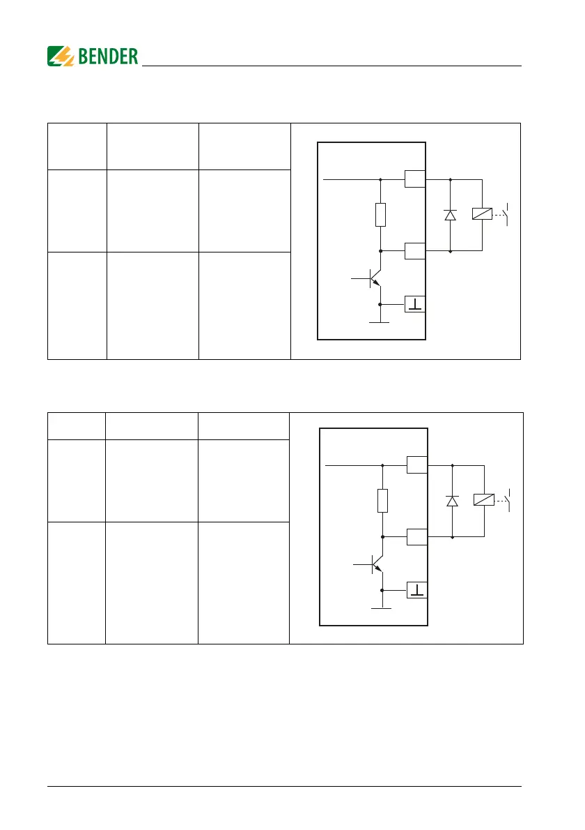
9.2.1 Use of Q1: Device health
1)
The SERVICE LED is also on
9.2.2 Use of Q2: Pulser
9.3 Digital input
The input is only detected as "activated" after the contact has been activated for at
least 150 ms. This way, short interference pulses are ignored.
For further information, refer to page 30.
Mode
No device
error detected
Device error
detected
1)
Fail-safe
on
energized
Q1 low
off
de-energized
Q1 high
Non-
fail-safe
off
de-energized
Q1 high
on
energized
Q1 low
Mode Inactive Active
Fail-safe
on
energized
Q2 low
off
de-energized
Q2 high
Non-
fail-safe
off
de-energized
Q2 high
on
energized
Q2 low
Pull up
10 kΩ
X1
+24 V,
max. 100 mA
+
24 V,
max. 300 mA
Q1
Intern. 24 V
Pull up
10 kΩ
X1
+24 V,
max. 100 mA
+
24 V,
max. 300 mA
Q2
Intern. 24 V