Connection
26
NGRM7xx_D00292_07_M_XXEN/02.2022
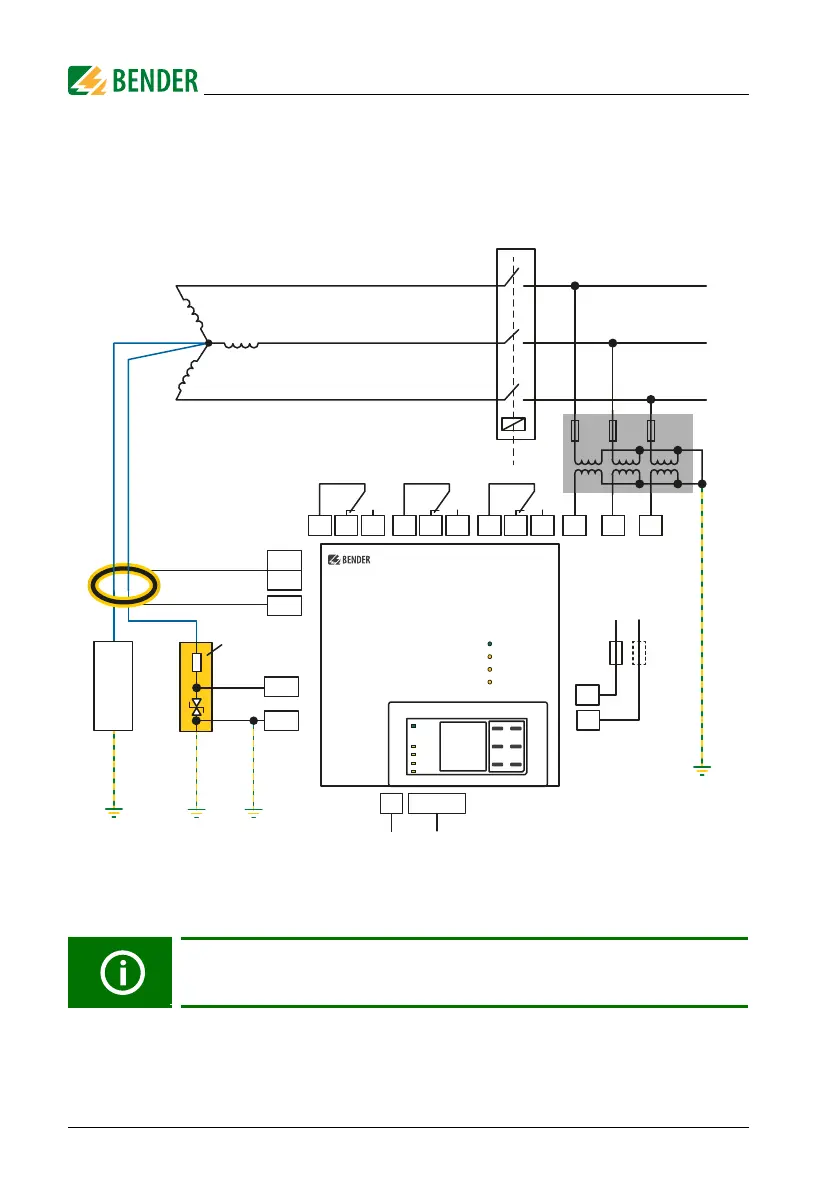
5.3.3 Connection U
sys
> 690 V
For these voltages, the phase monitor of the NGRM7… can only be connected to the
conductors to be monitored via potential transformers (PT).
Fig. 5.3: Star configuration (U
sys
> 690 V)
Note:
* PT ratio "primary: secondary" can be adjusted in the NGRM7…
The "N" connection of the CD-series coupling device should be as close to
the transformer star point as possible.
R
s
(G1)
E (G)
N
CD...
PE PE
R
S
E
k
l
NGR
CT
L1
L2
L3
L1 L2 L3
6A 6A 6A
PT *
LINETRAXX®
NGRM7…
A1
A2
X1
Ethernet
5
C
50m
6A
AC/DC
48...240 V
6A
11
12 14
21
22 24
31
32 34
Circuit breaker
NGR fault
Ground fault
Trip