3
104
7
ENGINE CHECKS AND ASSEMBLY
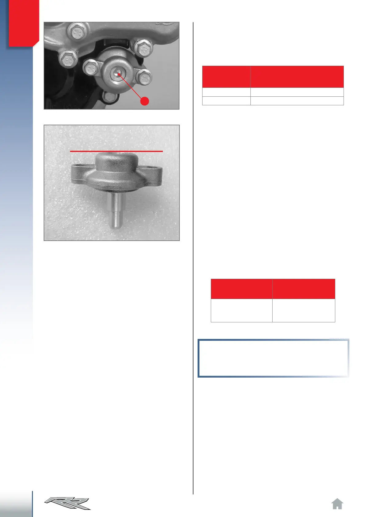
Intervene on screw 7 for the dynamic adjustment
of the exhaust valve unit, thus modifying the char-
acteristic curve of the engine.
The positions indicated in the table below are
those considered optimal for engine operation.
The "fully open" position is for perfect alignment
between adjustment screw head and adjustment
cover.
Adjustment must, therefore, be carried out as fol-
lows.
∙ Bring the screw to the “fully open” position;
∙ Tighten the number of turns indicated in the
table.
ATTENTION!
Do not tighten the adjustment screw for more
than three and a half turns from the fully open
position.
Displacement
[cm³]
Regulation of adjustment screw
(from all open)
250 1 + 1/2
300 1
Fully open reference.
Clockwise rotation
of adjustment screw
Anti-clockwise
rotation of
adjustment screw
Softer flow-rate and
less over-rev
Greater acceleration
and lower torque at
low speeds
The table shows the effects obtained from mod-
ifying the position of the adjustment screw with
respect to the positions in the above table.