3
98
10Nm
6
7
8
10Nm
ENGINE CHECKS AND ASSEMBLY
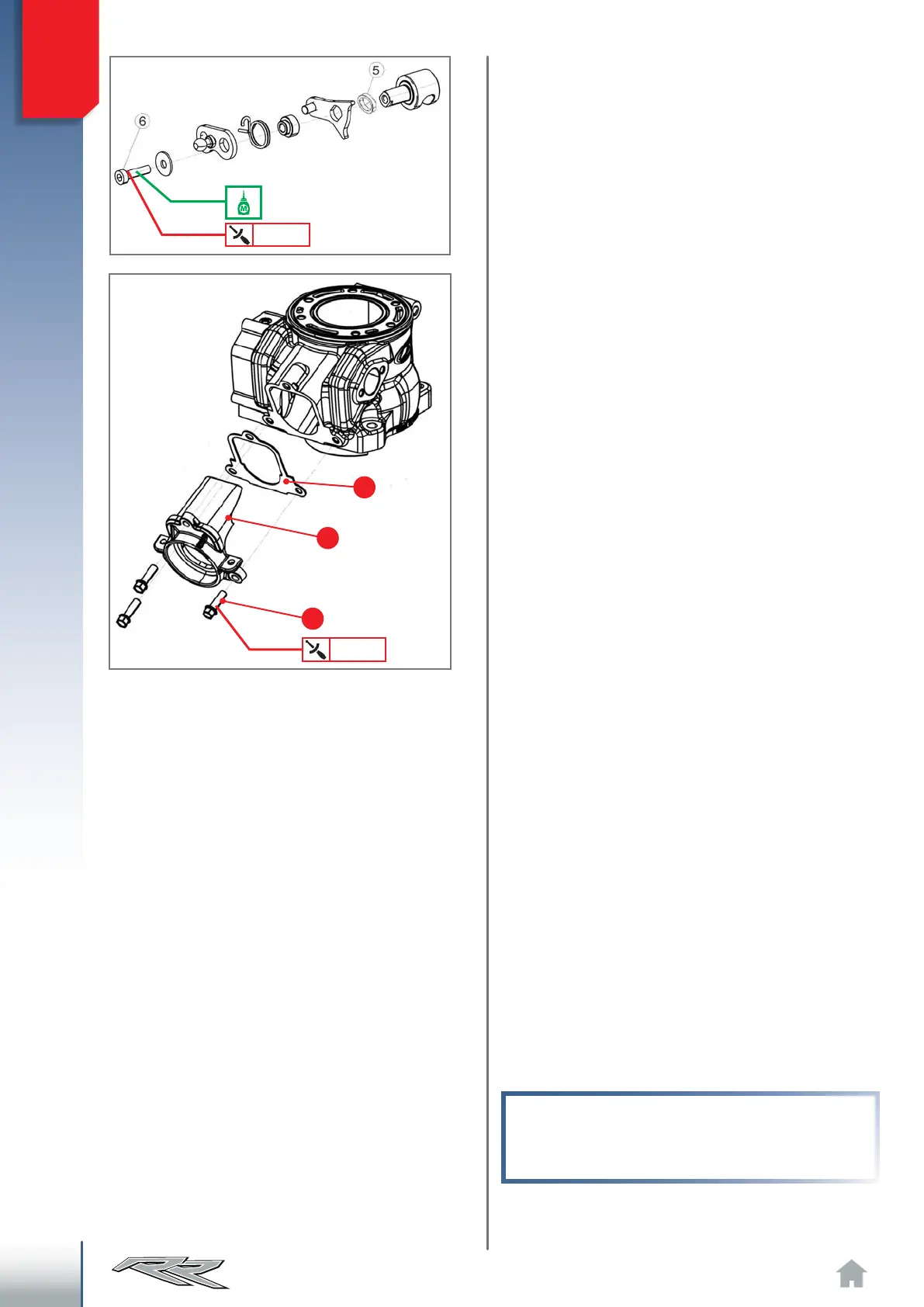
3.12.6 PISTON, PIN BOLT, ELASTIC
BANDS AND CYLINDER AS-
SEMBLY
Insert a circlip for retaining the pin bolt in one of
the seats on the piston's side, placing the circlip's
open part either upwards or downwards.
Apply the roller cage in the connecting rod's foot,
and lubricate it.
Oil pin bolt and seat in piston. Insert the pin bolt
in the piston from the side opposite where the
circlip was inserted, leaving enough space to
allow the connecting rod to mate with the piston.
Place the piston so that the arrow stamped on the
crown is facing the front of the engine (exhaust
opening). Couple the piston to the connecting
rod by fully pushing the pin bolt until flush with
the previously inserted circlip. It may be helpful
to use an aluminium cylinder (or similar tool)
during this phase.
WARNING!
Place a clean cloth between the piston and the
crankcase to keep foreign objects from falling
inside the base.
Apply spacer 5 to the control side.
Then apply all other parts.
Screw 6 must be covered with medium strength
threadlocker and fastened to the indicated torque.
Try moving the assembly and check the entire
mechanism slides perfectly, once assembly is
completed.