3
68
14
3
B
A
ENGINE CHECKS AND ASSEMBLY
3.7.2 Assembly of kickstarter
device - Optional
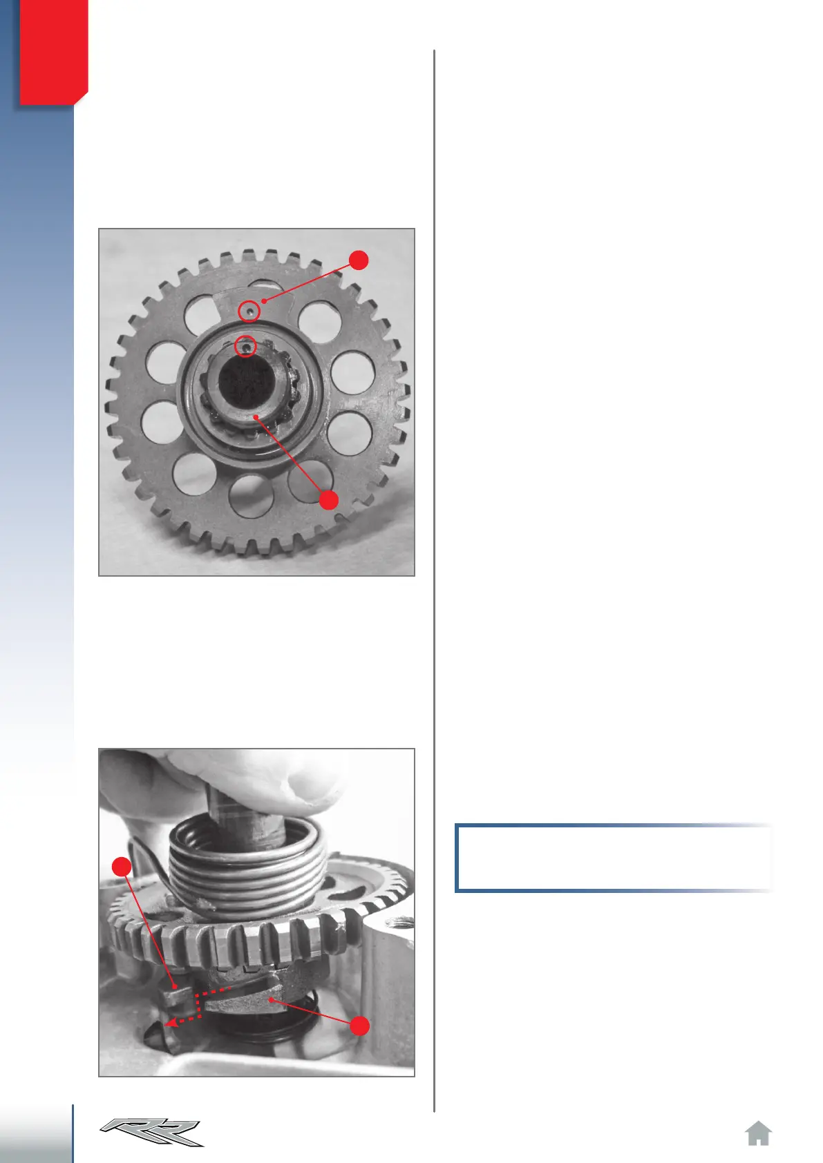
Insert the complete kickstart shaft in its housing,
keeping the thin-striped facing outwards and mak-
ing sure that the ramp A on the kickstart sleeve
is positioned below the ramp B bolted onto the
right crankcase half (external side).
Note: to fit the ramp A refer to para. “3.1.1
Specific applications of the right hand crank
case”.
Remove the kickstart spacer 9, expand the circlip
10, allowing for the removal of washer 11, of kick-
start gear 2 together with roller bearing 12 and
washer 11. This frees the kickstart shaft 3 from all
other parts.
Make sure that the side of the kickstart gear teeth
2 has no signs of meshing or notable superficial
wear. Make sure that the front teeth (sleeve side
14) are not chipped. Replace any part that shows
the aforementioned defects.
Make sure that the front teeth of the sleeve 14
are not chipped and that the spring 16 is capable
of exerting enough pressure on the sleeve 14 so
that this can pull the wheel 2.
Also check to make sure that no washers have
any abnormal or excessive wear. If so, replace
them. Make sure that the spring 8 has no cracks
or abnormal deformation. Replace if it is not able
to bring the external kickstart lever back to the
rest position.
For reassembly, follow the above disassembly
procedure in reverse order.
Pay attention to the correct positioning of the
sleeve 14 in respect to the shaft 3. The front of
the shaft has a reference sign, just as the sleeve
14 does: the two references must match.
Positioning of sleeve on small shaft.
Positioning of sleeve A below lever B.