44 support@solowavedesign.com
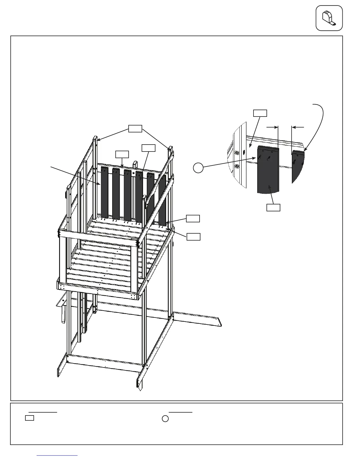
Step 15: Upper Swing Wall Assembly
HardwareWood Parts
6 x Cedar Wall 1 x 4 x 28”
5265
24 x #8 x 1-1/8” Wood Screw
A: Inbetweenboth(2153)PostsonSwingWallsideattach6(5265)CedarWallsto(2126)SWFloorand
(2106)SWTopusing4(S1)#8x1-1/8”WoodScrewsperboard.Makesurethebottomoftheboardsaretight
against(2147)EndBoardandthebevelledendsareatthetopandfacingout.Evenlyspaceboardsasshown
below.Spacingmustbe2-1/4”inbetweenallboards.(g.15.1and15.2)
Fig. 15.2
Fig. 15.1
S1
5265
2153
2106
2126
2147
x24
Bevellededges
facingout
Evenlyspaced
2106
2-1/4”
Swing Wall
S1
x6
5265