40 support@solowavedesign.com
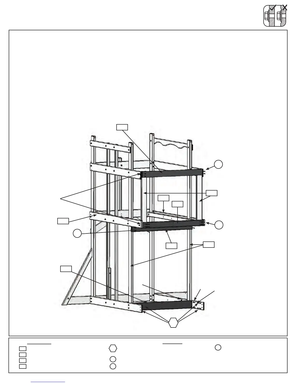
Step 12: Slide Wall Assembly
1 x Lower Bench 1 x 4 x 38-7/8”
1 x SL Floor End 2 x 4 x 38-7/8”
1 x Lower Floor Support 5/4 x 4 x 38-7/8”
1 x Side Ground 1 x 5 x 38-3/4”
2144
2122
A:Looselyattach(2127)SideGroundtotheoutsideofeach(2153)PostontheSlideWallsidewith4(H4)1/4x
4”HexBolts(withlockwasher,atwasherandt-nut).(g.12.1)
B:Attach(2122)SLFloorEndushtothebottomofeach(2112)SLPostwith8(S3)#8x2-1/2”WoodScrews.
(g.12.1)
C: Tighttothebottomof(2123)BackFloorand(2124)FrontFloorandushtotheoutsideedgesof(2153)
Postsattach(2103)LowerFloorSupportwith4(S7)#12x2”PanScrews.(g.12.1)
D:Attach1(2144)LowerBenchushtothetopsofeach(2112)SLPostwith4(S2)#8x1-1/2”WoodScrews.
(g.12.1)
Hardware
Wood Parts
1/4”
t-nut
Fig. 12.1
2144
Slide Wall
Back
1/4”lock
washer
1/4”at
washer
x4
4 x 1/4 x 4” Hex Bolt
(1/4” lock washer, 1/4” at washer, 1/4” t-nut)
4 x #8 x 1-1/2” Wood Screw
4 x #12 x 2” Pan Screw
S2
H4
S7
x4perside
H4
x4
S2
S7
S3
2122
2103
ush
2112
2124
Front
2153
S3
8 x #8 x 2-1/2” Wood Screw
2103
2127
2127
2123