45 support@solowavedesign.com
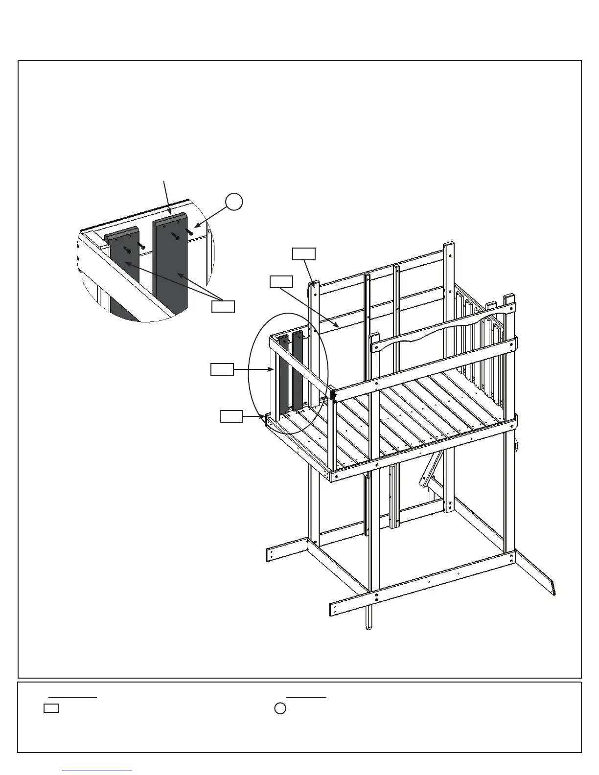
Step 16: Upper Front Wall Assembly
Part 1
HardwareWood Parts
2 x Cedar Wall 1 x 4 x 28”
5265
8 x #8 x 1-1/8” Wood Screw
S1
A: OntheSlideWallside,inbetween(2112)SLPostand(2153)PostontheFrontWall,evenlyspaceand
attach2(5265)CedarWallsto(2125)MiddleFrontand(2124)FrontFloor,using4(S1)#8x1-1/8”Wood
Screwsperboard.Makesurethebottomoftheboardsaretightagainsttheoorboardsandthebevelledends
areatthetopandfacingout.(g.16.1and16.2)
Fig. 16.2
5265
x4perboard
Bevellededges
facingout.
Fig. 16.1
S1
Evenlyspace
2153
2125
2112
2124
Slide Wall
Front Wall