49 support@solowavedesign.com
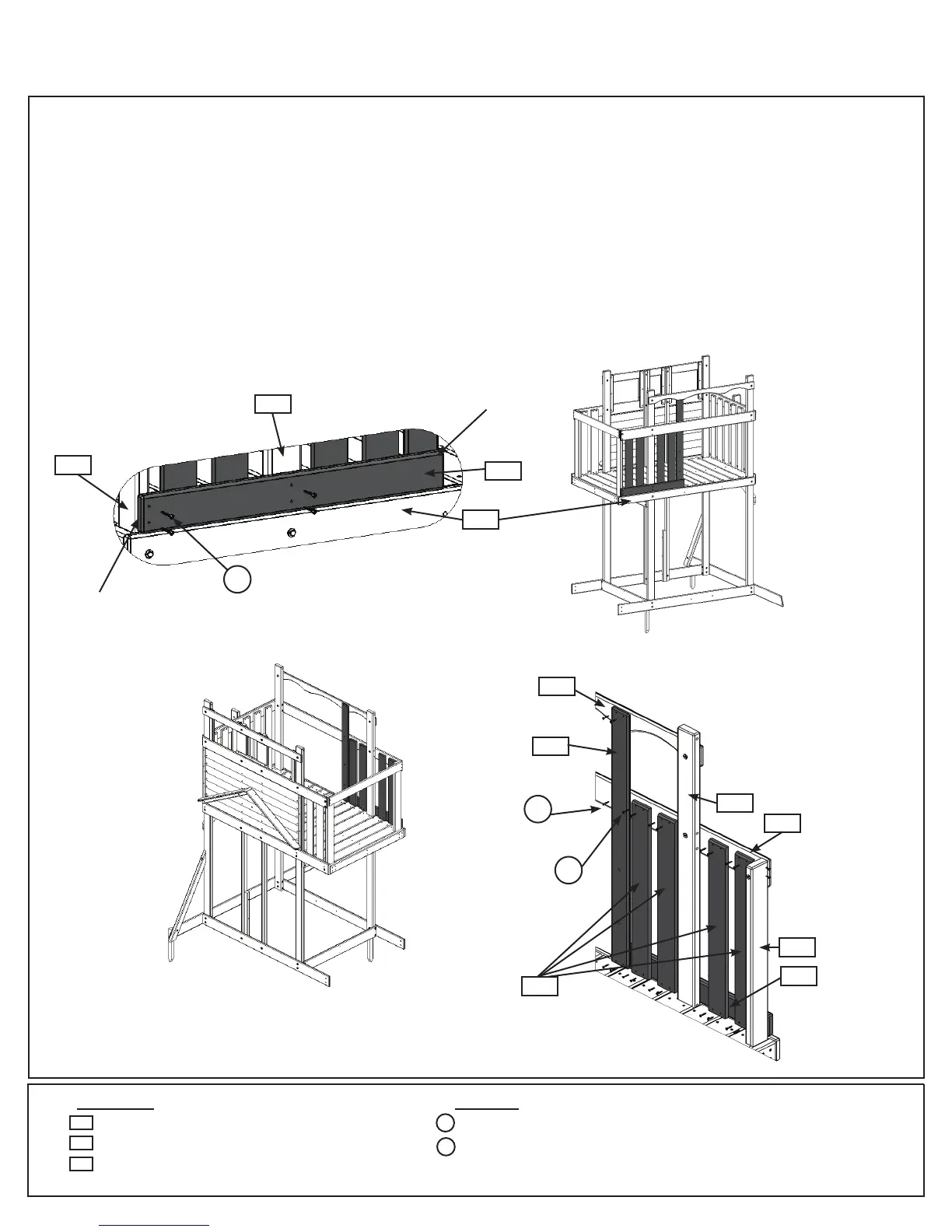
A: Tighttothetopof(2123)BackFloorandushtotheoutsideedgeof(2112)SLPostattach(2151)BackWall
Supportto(2112)SLPostand(2153)Postwith4(S7)#12x2”PanScrews.(g.17.1and17.2)
B:Flushtotheoutsideedgeof(2151)BackWallSupportandtighttotheoorboardsattach(1205)CEAccess
Wallto(2151)BackWallSupport,(2143)MiddleBackand(2145)BackTopwith5(S1)#8x1-1/8”WoodScrews,
asshowning17.2and17.4.
C: Evenlyspaceandattach4(5265)CedarWallsto(2151)BackWallSupportand(2143)MiddleBackwith4
(S1)#8x1-1/8”WoodScrews,asshowning17.1,17.2,17.3and17.4.Makesurethebottomoftheboards
aretightagainsttheoorboardsandthebevelledendsareatthetopandfacingout.
Step 17: Upper Back Wall Assembly
HardwareWood Parts
4 x Cedar Wall 1 x 4 x 28”
1 x CE Access Wall 1 x 4 x 41-3/4”
1 x Back Wall Support 5/4 x 4 x 31”
5265
21 x #8 x 1-1/8” Wood Screw
4 x #12 x 2” Pan Screw
S1
Fig. 17.2
Back Wall
x4
Fig. 17.1
Fig. 17.3 Fig. 17.4
S7
Outside View
Back Wall
Outside View
Inside View
2112
2151
Flush
2153
Flush
2123
2145
2153
2143
2112
2151
1205
5265
S1
x5
1205
Inside
View
S7
S1
x4per
board
2151