62 support@solowavedesign.com
2 x 1/4 x 1-1/2” Lag Screw (1/4”at washer)
2 x 1/4 x 1” Hex Bolt (1/4” lock washer, 1/4” at washer, 1/4” t-nut)
4 x #8 x 1-1/8” Wood Screw
HardwareWood Parts Other Parts
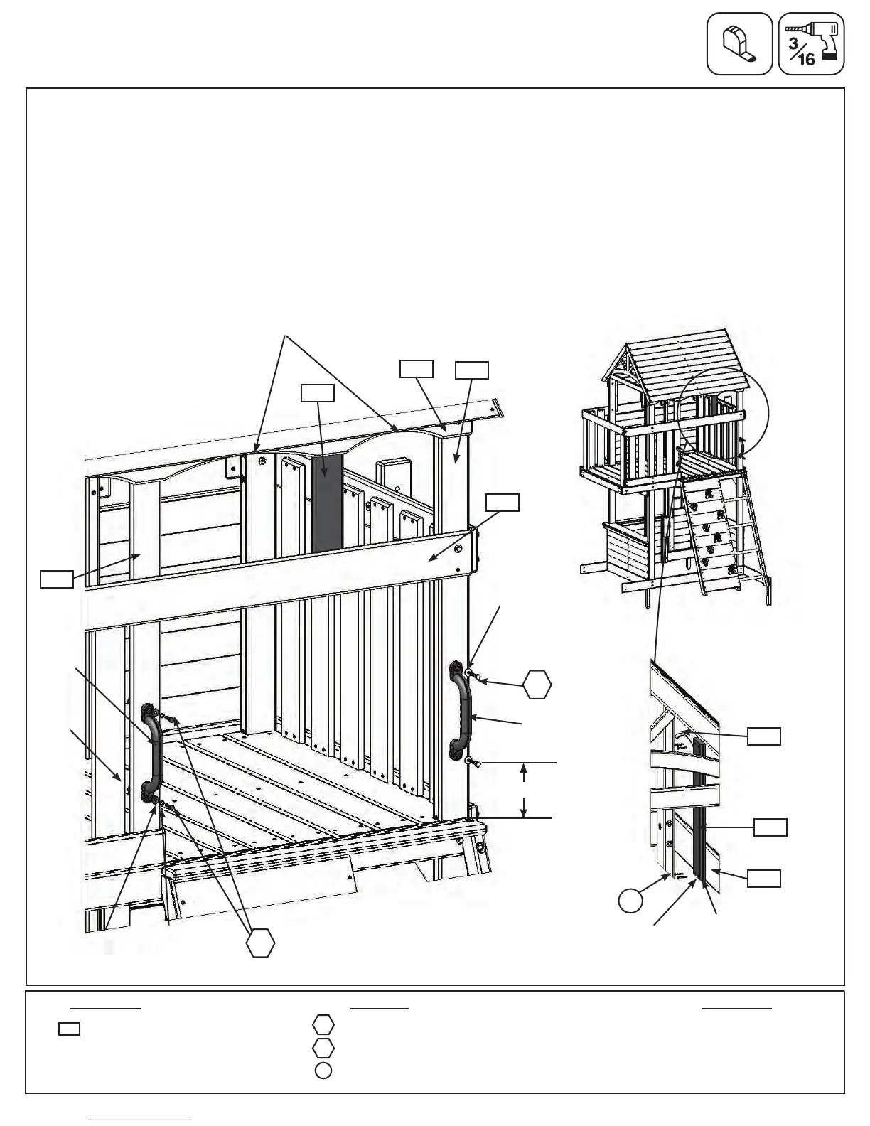
Step 25: Attach Hand Grips and Wall Board to Fort
Pre-drill all holes using a 3/16” drill bit before installing the Lag Screws
A:Measure6-1/2”upfromtheoorboardson(2153)Postthenattach1HandGripwith2(LS1)1/4x1-1/2”Lag
Screws(withatwasher).(g.25.1and25.2)
B:AttachasecondHandGripto(1205)CEAccessWallusingtheboltholes,with2(H0)1/4x1”HexBolt(with
lockwasher,atwasherandt-nut).(g.25.2)
C:Flushtothebottomof(2125)MiddleFrontandcentredbetweenthearchesof(2145)BackTop,asshown
ing.25.1,attach(0850)CEWallBoardwith4(S1)#8x1-1/8”WoodScrews.Bevellededgefacesdownand
towardsinsideoffort.(g.25.2and25.3)
LS1
2 x Hand Grips
Fig. 25.2
1/4”at
washer
1/4”
t-nut
1/4”at
washer
Fig. 25.1
Fig. 25.3
H0
1/4”lock
washer
LS1
x2
6-1/2”
S1
x4
Flush
2125
Hand
Grip
1205
0850
2153
2125
View from inside
2145
H0
1 x CE Wall Board 1 x 4 x 17”
0850
Arches
2145
HandGrip
S1
Bevellededge
facingdownand
towardsinsideof
fort
0850