56 support@solowavedesign.com
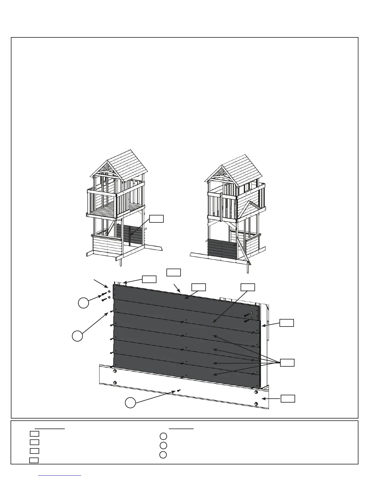
Step 21: Lower Swing Wall Assembly
A:Tighttothetopof(2157)GroundSWSideandushtotheoutsideedgesofboth(2153)Postsonthe
SwingWallsideattach4(2116)Sidingtoeachpostwith2(S0)#8x7/8”TrussScrewsperboard,asshownin
g.21.1and21.2.Makesuretherearenogapsbetweenboards.
B: Tighttothetop(2116)Sidingandushtooutsideedgesofboth(2153)Postsattach(2155)SidingNarrow
toeachpostwith2(S0)#8x7/8”TrussScrewsasshowning.21.3.
C:Place(2144)LowerBenchtighttothetopof(2155)SidingNarrowandushtotheoutsideedgesofboth
(2153)Poststhenattachtopostswith4(S7)#12x2”PanScrews(withatwasher).(g.21.3)
D: Frominsidetheassemblyplace(2139)SWWallSupportoverthecentrepilotholesofthe(2116)Siding
and(2155)SidingNarrowandushtothetopof(2144)LowerBenchthenattachfromoutsideoftheassembly
with1(S0)#8x7/8”TrussScrewpersidingand1(S1)#8x1-1/8”WoodScrewin(2157)GroundSWSide.
(g.21.2and21.3)
Hardware
Wood Parts
4 x #12 x 2” Pan Screw (3/16” at washer)
15 x #8 x 7/8” Truss Screw
2 x #8 x 1-1/8” Wood Screw
S7
1 x Lower Bench 1 x 4 x 38-7/8”
1 x Siding Narrow 3/8 x 3 x 38-3/4”
4 x Siding 3/8 x 3-1/2 x 38-3/4”
1 x SW Wall Support 5/4 x 2 x 23-1/2”
2144
S0
2155
Fig. 21.2
2153
Inside View
2139
S0
S7
3/16”at
washer
x4
x3perboard
2153
2144 2155
2116
2157
Swing Wall
Outside View
2116
2139
2139
(hidden)
Fig. 21.1
Fig. 21.3
S1
S1