38 support@solowavedesign.com
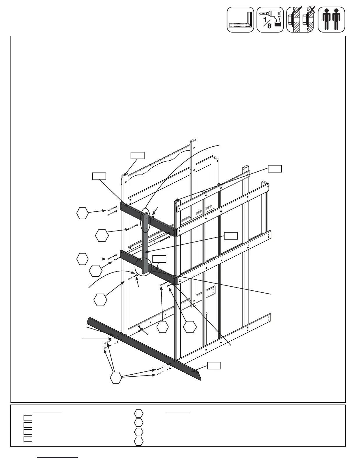
A:WithatleastoneadulthelperholduptheFrontandBackWallsandlooselyattach(2157)GroundSWSide
using4(H4)1/4x4”HexBolts(withlockwasher,atwasherandt-nut),(2126)SWFloorusing2(H5)1/4x
4-1/2”HexBolts(withlockwasher,atwasherandt-nut)inthetopholesand(2106)SWTopusing4(H5)1/4x
4-1/2”HexBolts(withlockwasher,atwasherandt-nut)toboth(2153)Posts.(g.11.1)
B:Looselyattach(2130)SWMountto(2126)SWFloorandto(2106)SWTopwith2(G5)5/16x4-1/2”Hex
Bolts(withlockwasher,atwasherandt-nut).KeeptheseboltslooseuntilStep13,Part1.(g.11.1)
Note: Pre-drill all holes using a 1/8” drill bit before installing the lag screws.
C:Makesuretheassemblyissquarethentightenall1/4”HexBoltsfromthisstep.Attach(2126)SWFloorto
each(2153)Postwith2(LS3)1/4x3”LagScrew(withatwasher).(g.11.1)
Step 11: Swing Wall Assembly
Part 1
2 x 5/16 x 4-1/2” Hex Bolt (5/16” lock washer, 5/16” at washer, 5/16” t-nut)
4 x 1/4 x 4” Hex Bolt (1/4” lock washer, 1/4” at washer, 1/4” t-nut)
6 x 1/4 x 4-1/2” Hex Bolt (1/4” lock washer, 1/4” at washer, 1/4” t-nut)
2 x 1/4 x 3” Lag Screw (1/4” at washer)
1 x SW Top 5/4 x 5 x 38-3/4”
1 x SW Mount 2 x 4 x 34-1/2”
1 x SW Floor 5/4 x 5 x 38-3/4”
1 x Ground SW Side 1 x 5 x 81-1/8”
2106
2126
2130
G5
1/4”lock
washer
1/4”at
washer
1/4”
t-nut
HardwareWood Parts
H5
H4
Fig. 11.1
2106
2126
2157
2130
2153
LS3
G5
LS3
H5
G5
H4
H5
H5
2157
LS3
2153
Notice holes towards top.
1/4”at
washer
5/16”at
washer
5/16”lock
washer
x4
Front Wall
Back Wall
5/16”
t-nut
Notice pilot holes are
above bolt hole (not
shown in picture)