69 support@solowavedesign.com
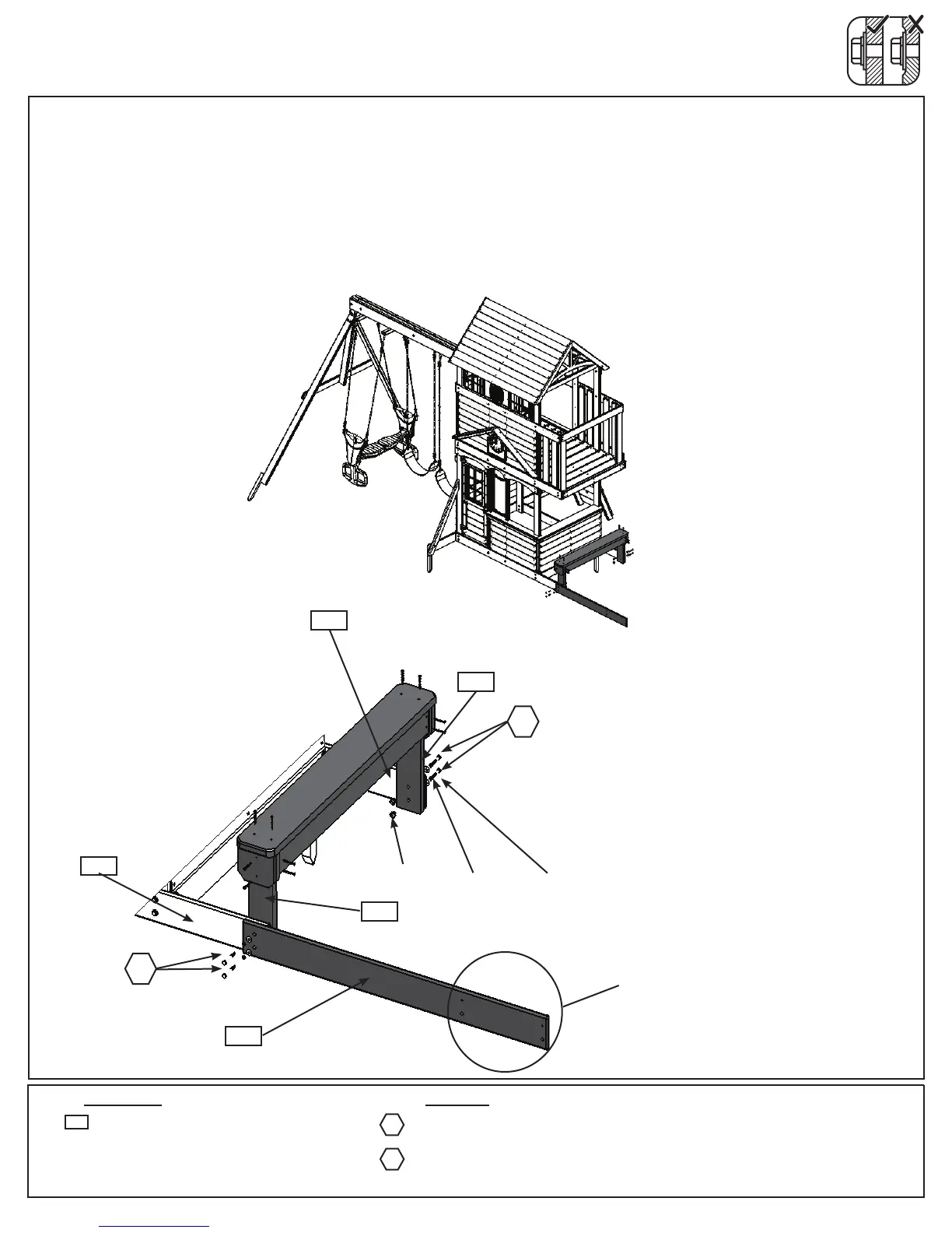
Step 32: Attach Bench to Fort
A:PlaceBenchAssemblyfromStep7betweenboth(2150)FrontBackGroundontheSlideWall.Attach
(2105)BenchPostsontheBackWallsideto(2150)FrontBackGroundwith2(H1)1/4x1-1/2”HexBolts
(withlockwasher,atwasherandt-nut).(g.32.1and32.2)
B:Attach(2110)SlideGroundto(2150)FrontBackGroundand(2105)BenchPostwith2(H2)1/4x2”Hex
Bolts(withlockwasher,atwasherandt-nut).Noticetheboltholesattheendoftheboardshouldbetowards
thebottomoftheboard.(g.32.2)
Hardware
2105
2 x 1/4 x 1-1/2” Hex Bolt
(1/4” lock washer, 1/4” at washer, 1/4” t-nut)
2 x 1/4 x 2” Hex Bolt
(1/4” lock washer, 1/4” at washer, 1/4” t-nut)
H1
2150
2105
Fig. 32.1
Slide Wall
1/4”lock
washer
1/4”at
washer
1/4”
t-nut
Front Wall
Back Wall
Fig. 32.2
H1
H2
2150
Noticehole
locations
2110
H2
1 x Slide Ground 1 x 5 x 44-3/4”
2110
Wood Parts