53 support@solowavedesign.com
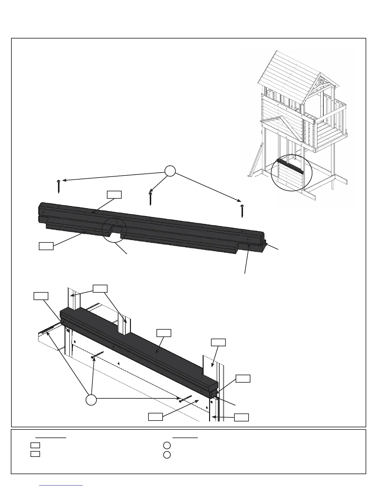
Step 19: Lower Front Wall Assembly
Part 2
E:Place(2102)FrontTableSupportontopof(2131)FrontTable
Top,withfacesandendsush,asshowning.19.4.Noticethe
holein(2102)FrontTableSupportiscentredoverthenotchedout
sectionof(2131)FrontTableTopandattachusing3(S7)#12x2”
PanScrews.
F:PlaceTableTopAssemblytighttothetopof(2160)Narrow
Siding,(0389)WindowFrameand(2133)Trimsothemiddlenotch
tsaroundcentre(2154)FrontPost.Makesure(2102)FrontTable
Supportistightto(2153)Postandboth(2154)FrontPoststhen
attach(2102)FrontTableSupporttoeachpostusing1(S3)#8x
2-1/2”WoodScrewperpost.(g.19.5and19.6)
Hardware
Wood Parts
3 x #12 x 2” Pan Screw
3 x #8 x 2-1/2” Wood Screw
S7
1 x Front Table Support 2 x 2 x 32”
1 x Front Table Top 5/4 x 4 x 32-1/16”
2102
S3
2131
2131
Fig. 19.4
Flush
2153
Tight
Notice hole orientation in (2102)
Front Table Support
2102
2131
Flush
S7
Fig. 19.6
S3
0389
2102
2160
2133
2154
Front Wall
Fig. 19.5