72 support@solowavedesign.com
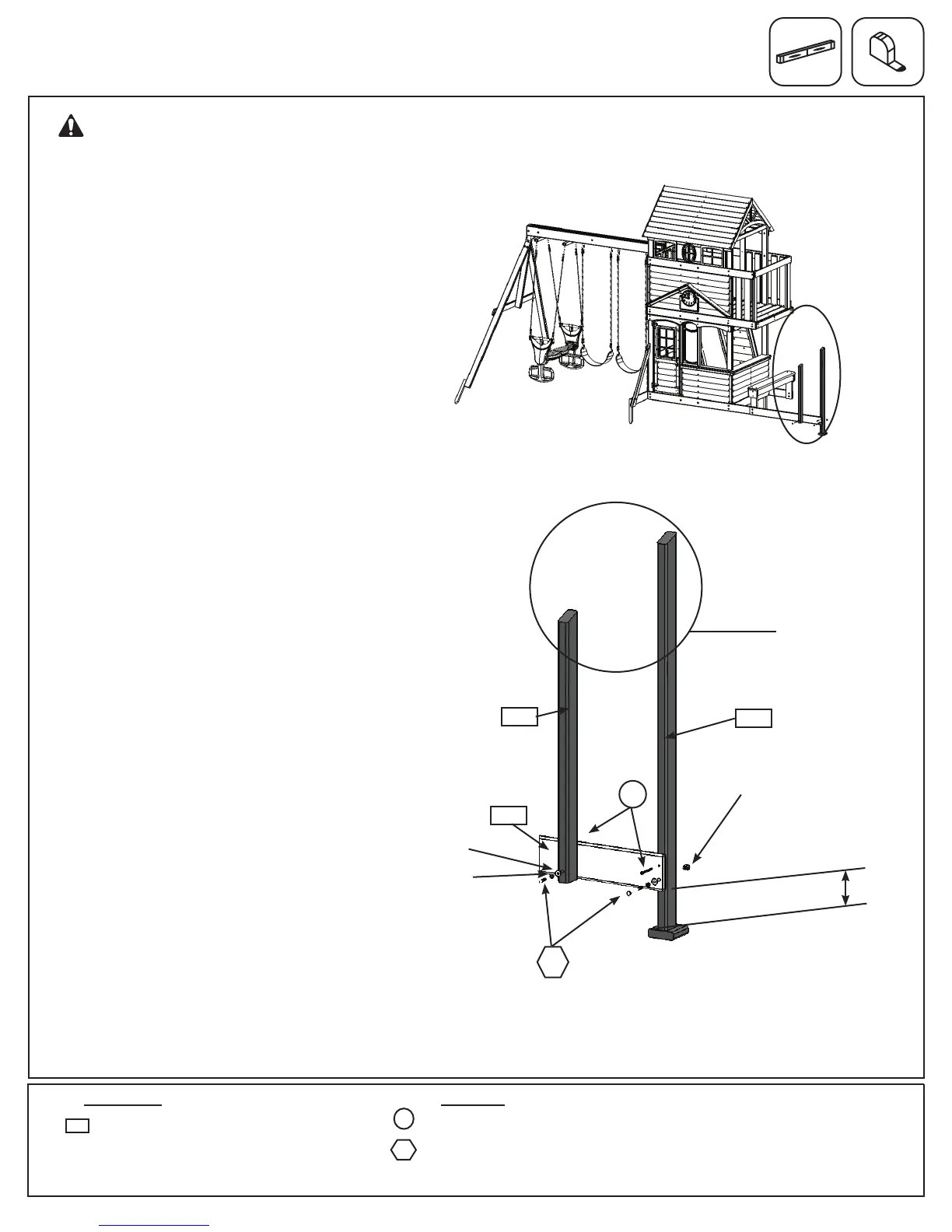
Step 34: Slide Support Assembly
Part 2
Fig. 34.2
Fig. 34.3
B:Attheendof(2110)SlideGrounddig
one,atbottom,8”wideby6”deepholeas
showning.34.3.Place(2137)SLUpright
inthehole,makingsurethatitisplumb.
Noticetheanglededgeslopestowards
(2110)SlideGround.(g.34.3)
C:Place(2140)ShortUprightbeside
(2137)SLUprightontheoppositesideof
(2110)SlideGroundmakingsurethatit
isplumb.Noticetheanglededgeslopes
awayfrom(2110)SlideGround.(g.34.2
and34.3)
D:Looselyattach(2140)ShortUprightand
(2137)SLUprightto(2110)SlideGround
with1(H12)1/4x3”HexBolt(withlock
washer,atwasherandt-nut)perboard.
(g.34.3)
E:Rellholehalfwaywithsoiland
compactmakingsure(2137)SLUpright
staysplumb.Finishllingandcompacting.
(g.34.3)
F:Tightenboltsin(2140)ShortUpright
and(2137)SLUprightthenattach(2110)
SlideGroundtouprightswith1(S3)#8x
2-1/2”WoodScrewperboard.(g.34.3)
WARNING: Digging can be
dangerous if you do not check rst for
underground wiring, cables or gas lines.
2137
6”
2140
2110
Anglededgesslope
towardsSideGround
H12
1/4”lock
washer
1/4”at
washer
1/4”
t-nut
1 x Short Upright 2 x 3 x 33”
HardwareWood Parts
2 x #8 x 2-1/2” Wood Screw
2 x 1/4 x 3” Hex Bolt
(1/4” lock washer, 1/4” at washer, 1/4” t-nut)
H12
2140
S15
S15