55
Chapter 6. Basic maintenance
CAUTION: Maintenance of the PhD Lite should only
be performed by appropriately trained personnel.
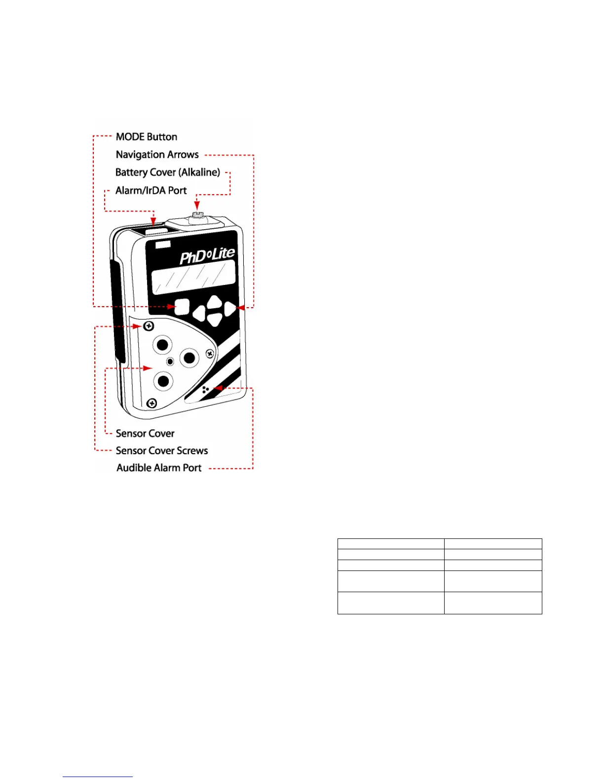
Figure 6.0 PhD Lite external features
6.1 Sensors
At instrument start up, the PhD Lite is designed to
recognize the “Smart Sensors” that are installed and
automatically set the appropriate alarm and display
readings. The PhD Lite automatically recognizes when
sensor changes have been made since the instrument
was last turned on.
Note: Any changes made to the sensors installed,
even changing one sensor for another of the exact
same type, will trigger a “Needs Cal” message the
next time the instrument is turned on. The PhD Lite
must be calibrated before being returned to service
following any sensor changes.
Caution: The PhD Lite must be turned off prior to
removing or replacing sensors.
6.1.1 Sensor replacement
Note: The PhD Lite must be turned off to replace
sensors.
1. Remove the three philips screws and take off the
sensor cover from the front of the instrument.
For replacement of an existing sensor perform
steps 2a and 3a then proceed to step 4a or 4b.
2a. From the outer surface of the sensor cover, use a
flat blade screwdriver to gently push out the metal
screen (if present), gasket & filter ring assembly.
Discard old gasket, filter ring assembly & metal
screen. The metal screen is not to be reused and
its absence will not affect sensor performance.
3a. Remove any remaining traces of adhesive from the
recessed hole in the sensor cover.
For new sensor installation perform steps 2b and 3b
then proceed to step 4a or 4b.
2b. From the outer surface of the sensor cover, push
out yellow dust cap with a blunt tool.
3b. Remove sensor blank from the sensor
compartment.
For Sensors O
2
, LEL, CO, CO Plus, CO-H, H
2
S, NO,
DUO-TOX perform step 4a then proceed to step 5.
4a. Firmly press the new filter ring assembly into the
recessed hole in the sensor cover with ridge side
up.
For Reactive Gas Sensors: SO
2
, NO
2
, PH
3
, HCN, Cl
2
,
ClO
2
perform step 4b then proceed to step 5.
4b. Firmly press the new teflon spacer into the
recessed hole in the sensor cover. For optimal
sensor response, no external filter element is used
with these sensors.
CAUTION: Since the reactive gas sensor face
is openly exposed to the ambient environment,
extra care should be taken to prevent water or any
other liquids from coming into contact and
remaining on the sensor face.
5. Peel the backing paper from the new rubber gasket
and center it over the newly mounted filter ring
assembly with the adhesive side down.
6. Remount sensor cover and secure with three
philips screws. DO NOT overtighten.
7. Install functional battery pack or batteries in the
detector.
8. New sensors must be allowed a stabilizing time –
with detector powered off and with functional
batteries or battery pack installed, according to the
following schedule.
Sensor Stabilization Period
Oxygen (54-25-90) 1 hour
LEL (54-25-80A) 5 minutes
All Toxic sensors except
those shown below
15 minutes
54-25-04 NH
3
Sensor
54-25-06 NO Sensor
24 hours
9. The PhD Lite will automatically recognize the
changes that have been made upon turn on and
display the “Warning Needs Cal” message.
10. Calibrate the PhD Lite with calibration gas
appropriate for the new sensor before the
instrument is put back into service.
11. If newly installed sensor(s) do not appear during
power-up, or if the message "not supported"