17
1. 87 7. 8 7 7. 2 2 6 9 BLACKBOX.COM
NEED HELP?
LE AVE THE TECH TO US
LIVE 24/7
TECHNICAL
SUPPORT
1. 87 7. 87 7. 2 26 9
CHAPTER 4: INITIAL INSTALLATION
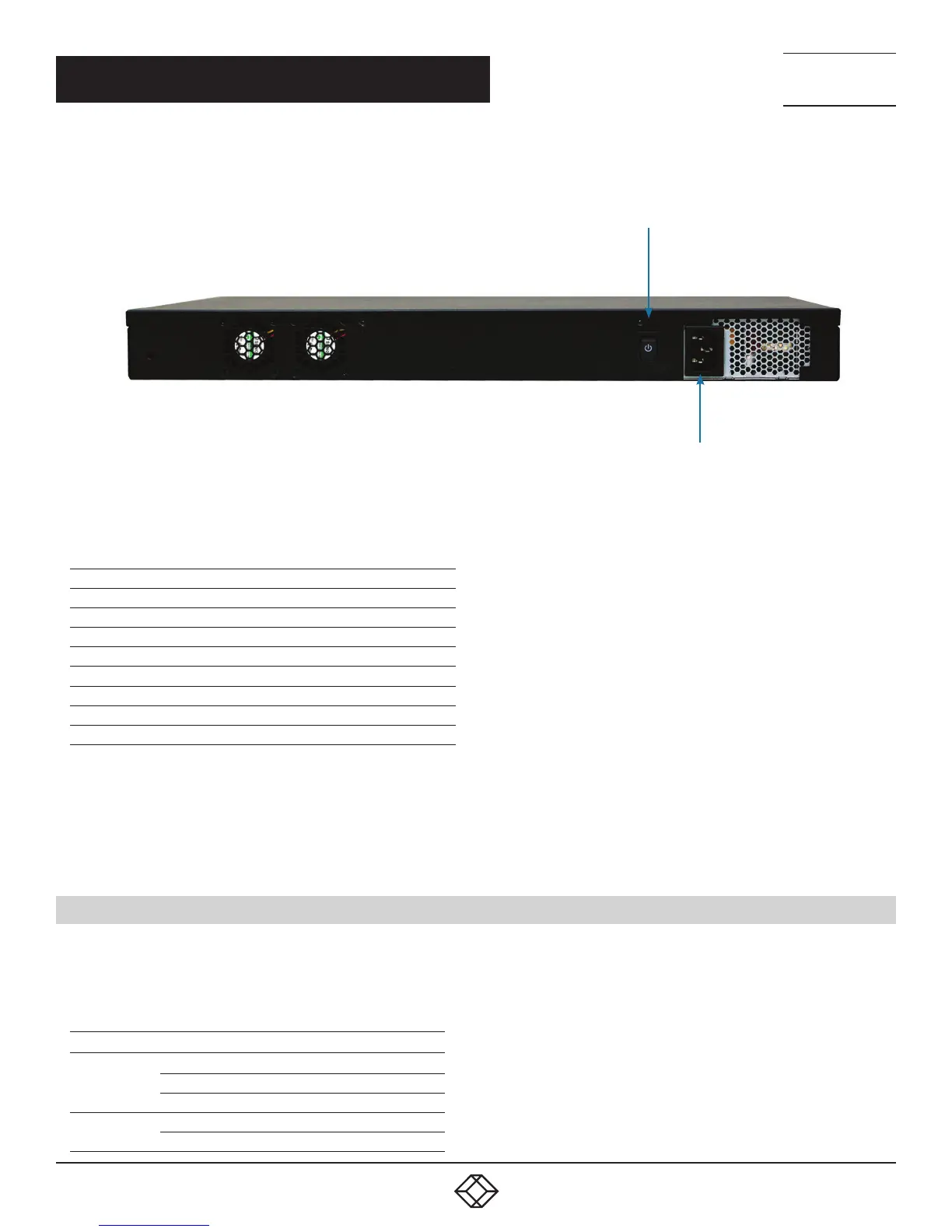
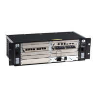
Power ON/OFF switch
Power supply connector
FIGURE 7. BOXILLA REAR PANEL
TABLE 4-2. PANEL COMPONENTS
COMPONENT DESCRIPTION
Serial port DB9 male console
DVI port Test interface
RJ-45 port Reserved for future use
Network port 1G Ethernet RJ-45 connector
(2) USB Type A ports USB 2.0, used for exporting log files
(2) USB Type A ports USB 3.0, used for exporting log files
Power switch ON/OFF switch
3-prong outlet 100–240 VAC, 50-60 Hz
CONNECT THE POWER
1. Locate the AC line cord.
2. Attach the AC line cord to the power supply connector on the rear of the unit.
3. Power up the unit by turning on the power switch on the back of the unit.
4.2 LED IDENTIFICATION
Two LEDs are built into the RJ-45 connectors on the Boxilla Manager. The definition of the operation of these LEDs is shown in
Table 4-3.
TABLE 4-3. RJ-45 CONNECTOR LEDS
LED INDICATION
MEANING
Speed
Green ON
1 Gbps link
Amber ON 100 Mbps link
OFF 10 Mbps link
Activity
Amber blinking Valid link
OFF No link