Mechanical Dock Leveler – M and FMC Group 14, Section 11, Page 1
Issue Date: 10/01/01, Rev, 0 (Part #038-550E)
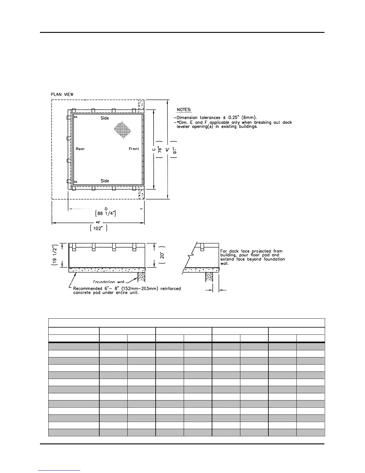
POUR-IN-PLACE DOCK LEVELER
c/w Pit Forming Walls - Details
DOCK LEVELER DIMENSION REFERENCE
MODEL SIZE C D *E *F
(W x L) In mm In mm In mm In mm
5' x 6' 66 1676 64.25 1632 85 2159 78 1981
6' x 6' 78 1981 64.25 1632 97 2464 78 1981
6' x 8' 78 1981 88.25 2242 97 2464 102 2591
6' x 10' 80 2032 112.25 2851 97 2464 126 3200
6' x 12' 80 2032 136.25 3461 97 2464 150 3810
6'6" x 6' 84 2134 64.25 1632 103 2616 78 1981
6'6" x 8' 84 2134 88.25 2242 103 2616 102 2591
6'6" x 10' 86 2184 112.25 2851 103 2616 126 3200
6'6" x 12' 86 2184 136.25 2461 103 2616 150 3810
7' x 6' 89 2261 64.25 1632 108 2743 78 1981
7' x 8' 89 2261 88.25 2242 108 2743 102 2591
7' x 10' 91 2311 112.25 2851 108 2743 126 3200
7' x 12' 91 2311 136.25 3461 108 2743 150 3810
IMPORTANT
Pit Perimeter Curb Angles
Must be level side-to-side and
front-to-back.
Must be square and parallel
to each other.
Finished floor to be flush with
upper surface.