Group 08, Section 17, Page 4 Mechanical Dock Leveler – M and FMC
Issue Date: 10/01/01, Rev, 0 (Part #038-550E)
LONGER LIP REQUIREMENT – cont’d
Move Dock Leveler Forward
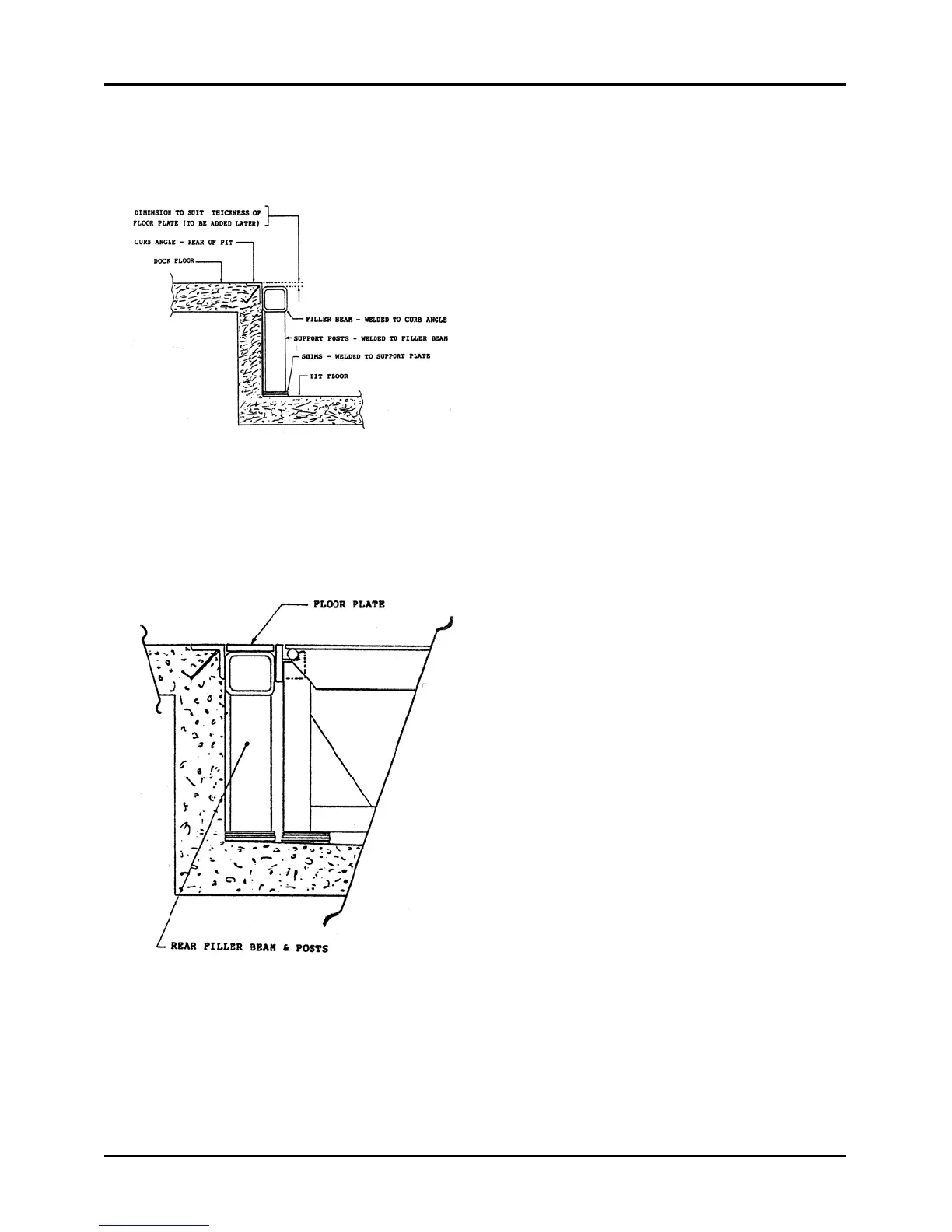
Fit and assemble the filler beam, support
posts and shims into the rear pit area as
shown in Figure 98. Assure the top
surface of the filler beam is parallel with
the top surface of the rear curb angle
and offset down to suit the thickness of
the floor plate that will be welded in as a
final step. Support posts can be fitted
and pre-welded to the filler beam.
Tack-weld the filler beam securely to the
rear and side curb angles, do not finish
weld at this time. Assure the support
post shims, if used, are located so as not
to interfere with the dock leveler frame
when it is moved back into place against
the face of the filler beam. Finish weld
these shims into place.
At this time, clean-up the top and rear
surface of the dock leveler back beam. If
shims were used between the back
beam and the curb angle in the original
installation, do not remove them, but
grind off any slag or remaining weld
material in the areas that were torch cut,
and weld the shims securely to the back
beam.
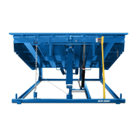
Clean the rear pit area and, using
appropriate equipment and/or tools,
move the dock leveler back into the pit
and into position against the filler beam,
Figure 99.
Check the rear corners of the dock
leveler for correct height. Top of back
beam to be at same level as top of rear
curb angle. If height is satisfactory,
tack-weld the back beam to the filler
beam at points of contact. If height is not
correct, shims must be added or deleted
under the back corners of the frame. To
accomplish this, the deck must be raised
to gain access to the pit area.
Figure 98
Figure 99