Mechanical Dock Leveler – M and FMC Group 08, Section 17, Page 3
Issue Date: 10/01/01, Rev. 0 (Part #038-550E)
LONGER LIP REQUIREMENT – cont’d
Move Dock Leveler Forward
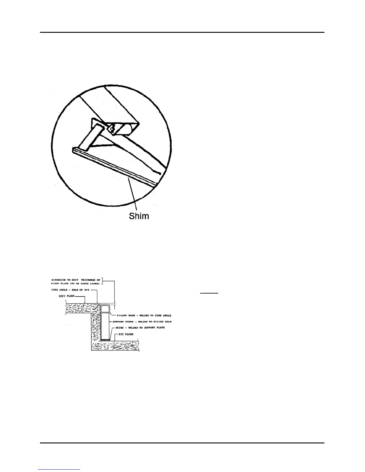
Inspect the lifting arm cam mounting
plate to determine if shims are located
between it and the pit floor. If shims are
present, move forward with the unit. See
Figure 96. Plate must be level front to
back.
Remove both dock bumpers.
When all retaining welds have been
removed and unit is free to be moved
forward, remove the safety stand and
lower the maintenance strut. Walk the
deck down to its stored position and
tack-weld a retaining strap between the
lip and the front frame or tack weld the lip
to the frame to assure the deck does not
raise as the dock leveler is being moved.
Using appropriate equipment and/or
tools, move the entire unit approximately
16" forward in the pit to allow working
space at the rear of the pit.
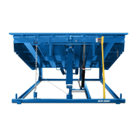
See Figure 97 for illustration of typical
rear filler beam, vertical supports and
shims.
Note: Vertical support posts must be
located under the filler beam in a quantity
that equals the quantity of vertical
supports in the dock leveler frame, with 3
supports being the minimum quantity
used. One at each outer end and one in
the centre.
Weld shims under the vertical posts if
required, to assure positive contact with
the pit floor for maximum support.
To eliminate any possibility of wide floor
cracks after completion, the rear filler
beam will be located 1/4" lower than the
dock floor and then be covered with a
1/4" thick floor plate to completely fill the
space between the curb angle and the
dock leveler back beam.
Figure 96
Figure 97