Group 08, Section 17, Page 2 Mechanical Dock Leveler – M and FMC
Issue Date: 10/01/01, Rev, 0 (Part #038-550E)
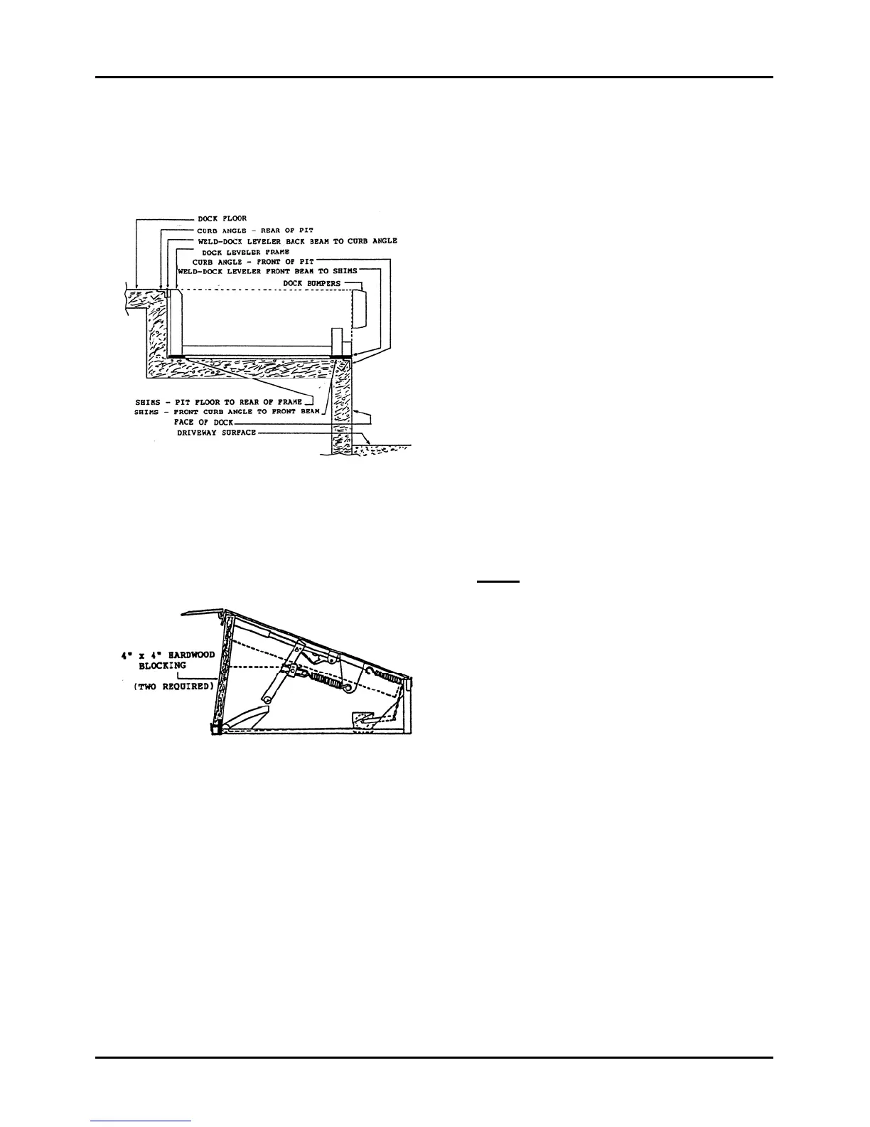
LONGER LIP REQUIREMENT – cont’d
Move Dock Leveler Forward
Figure 94, shows a side view of a typical
dock leveler installed in a standard pit.
Deck and lip are not shown.
Recommended weld areas are indicated.
These welds will be removed to allow
moving the unit forward.
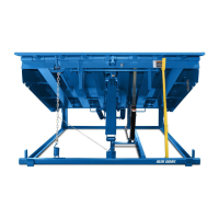
Raise dock leveler fully and position
maintenance strut and traffic barriers as
required for safety. Place a safety stand
between the deck assembly and the
lower frame to assure the deck can not
lower. If a safety stand is not available,
block as shown in Figure 95.
Thoroughly inspect the installation
method used and locate all areas of the
dock leveler frame that have been
welded to the pit curb angles or shims.
Note: If shims are located under the rear
frame, assure they will move forward
with the frame to maintain the present
frame height.
Back beam of dock leveler frame, to rear
curb angle of pit welds. Locate and cut
all welds, causing as little damage as
possible to the curb angle and back
beam.
Front beam of dock leveler frame, to
shims and/or front curb angle of pit
welds. Locate and cut welds in such a
way as to allow all shims to be removed
and discarded.
Figure 94
Figure 95