Mechanical Dock Leveler – M and FMC Group 08, Section 08, Page 1
Issue Date: 10/01/01, Rev. 0 (Part #038-550E)
LIP LOCK and SPRING ASSEMBLY REPLACEMENT
1) Raise dock leveler and position
maintenance strut and traffic barriers
as required for safety.
2) Manually lift lip to its fully raised
height. Measure from underside of tip
of lip to driveway surface. Cut 2 sound
pieces of 2” x 4” hardwood blocks to
this length.
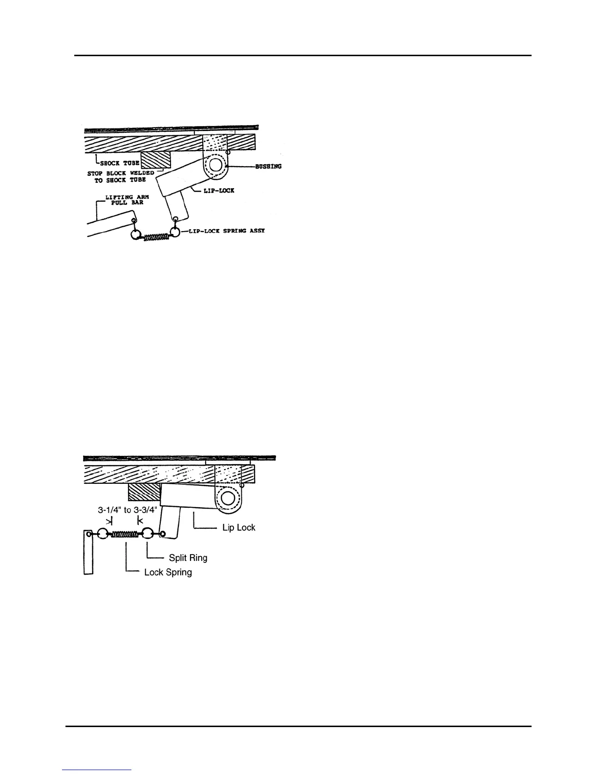
Figure 33
3) Lift the tip of the lip up and position the blocks vertically between the driveway and
the underside of the tip of the lip, to create a positive means of maintaining the lip in
its horizontal position
4) Enter the pit area and remove the lip lock spring assembly from the lip lock and the
lifting arm pull bar. See Figure 33.
5) Inspect the lip lock at this time to assure free rotation and that the pivot pin and
bushing do not have excessive wear. Lubricate thoroughly before installing the new
spring. Replace if damaged or faulty, as required.
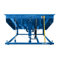
6) Install a new spring assembly onto the lip
lock and the lifting arm pull bar, orienting
the spring end eye's as shown in
Figure 34.
7) Remove the 2" x 4" lip blocks and lower
the lip to allow the lip lock to support the
lip in its extended position. The spring
body must measure 3-1/4” to 3-3/4” long
when deck is in fully raised position. If
spring body is too short, remove and
discard one split ring.
Figure 34
8) Lower the maintenance strut.
9) Walk the deck down to a position that places the top of the deck, at the lip hinge, at
12" above dock height. The lip lock should release the lip with the deck at this
height and at any deck height lower than 12" above dock.