Group 06, Section 03, Page 2 Mechanical Dock Leveler – M and FMC
Issue Date: 10/01/01, Rev, 0 (Part #038-550E)
LIP STRIKES REAR OF PARKED VEHICLE AS DECK RAISES – cont’d
The aim of this adjustment is to
have the lip begin to extend as late
as possible in the deck-upward
portion of the operating cycle while
retaining its ability to reach an
extended and locked position.
Model, capacity and length of lip will
affect the degree of improvement
that can be achieved, and dictates
the trial and error type of adjustment
described in the following text.
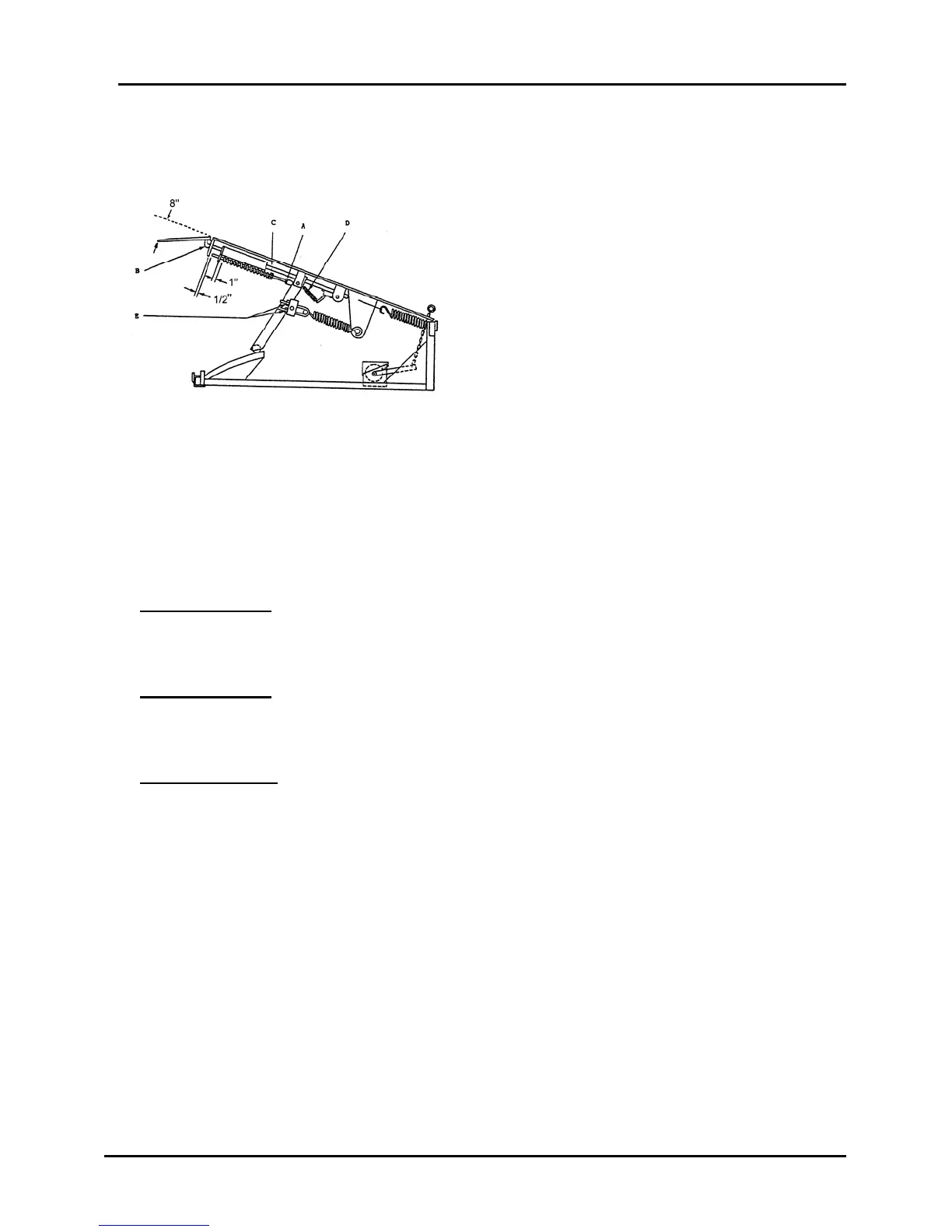
Figure 6A
Follow the standard sequence of Adjustment Steps described in Group 06,
Section 02, Pages 1 to 3, with the following changes to specified dimensions shown
in Figures 1 and 3.
Step Number 2: Adjust the shock rod and lip clevis to obtain a dimension of
8” rather then 6-3/4”, when measuring from the underside of the straight edge to the
underside of the tip of the lip.
Step Number 3: Adjust the lip assist spring adjusting nuts to obtain a dimension of
1” rather than 3/4” when meausring from the lip pusher plate to the end of the lip
assist spring.
Step Number 5: Higher than normal main lift spring tension will be required to
operate the dock leveler. Expect the effort required to lower the deck to be greater
than normal.
Continue to manipulate the main lift spring tension and the lip pusher plate to lip
assist spring dimension until the most acceptable combination is achieved, that
starts to extend the lip as late as possible in the deck –upward portion of the
operating cycle and mintains a deck lowering effort that is acceptable.