Mechanical Dock Leveler – M and FMC Group 02, Section 01, Page 3
Issue Date: 10/01/01, Rev. 0 (Part #038-550E)
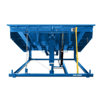
INTRODUCTION and COMPONENT IDENTIFICATION
Right & Left Side
The right side is identified by standing on the dock leveler
while facing the dock door and lip.
Base Frame
The angle iron mounting frame that is the base platform
for the entire dock leveler. It sits firmly on the bottom of
the dock pit and is the base that supports for the entire
leveler
Rear Frame Assembly
The rear portion of the Base Frame that contain the tilt
bar pockets.
Front Beam Assembly
Front of Base Frame that contains the Lip Keepers and
provides mounting points for other components.
Cam
The curved track that provides a ramp action. This ramp
action works in conjunction with the lifting arm, roller and
Main Lift Springs to elevate the deck.
Lifting Arm Roller
Attached to the lower end of the Lifting Arm, the Cam
Roller travels the contour of the Cam and allows smooth
low resistance movement while raising or lowering the
dock leveler deck.
Lifting Arm
When pulled rearward by the Main Lifting Springs this
arm rotates around it's pivot point and by so doing,
transfers motion to the appropriate components of the
deck leveler.
Main Lift Springs
Create the potential energy necessary to raise and
suspend the entire weight of the deck and lip.
Deck & Lip
The plates that become the bridge from the dock to the
truck floor
Tilt Bars & Pockets
Floating hinge points located at the rear of the deck that
allow the deck to float diagonally and compensate for
irregularities in lateral truck positioning.
Lip
This is the hinged plate on the outside edge of the deck.
It rests on the truck floor when the deck is in working
position.