Mechanical Dock Leveler – M and FMC Group 08, Section 09, Page 3
Issue Date: 10/01/01, Rev. 0 (Part #038-550E)
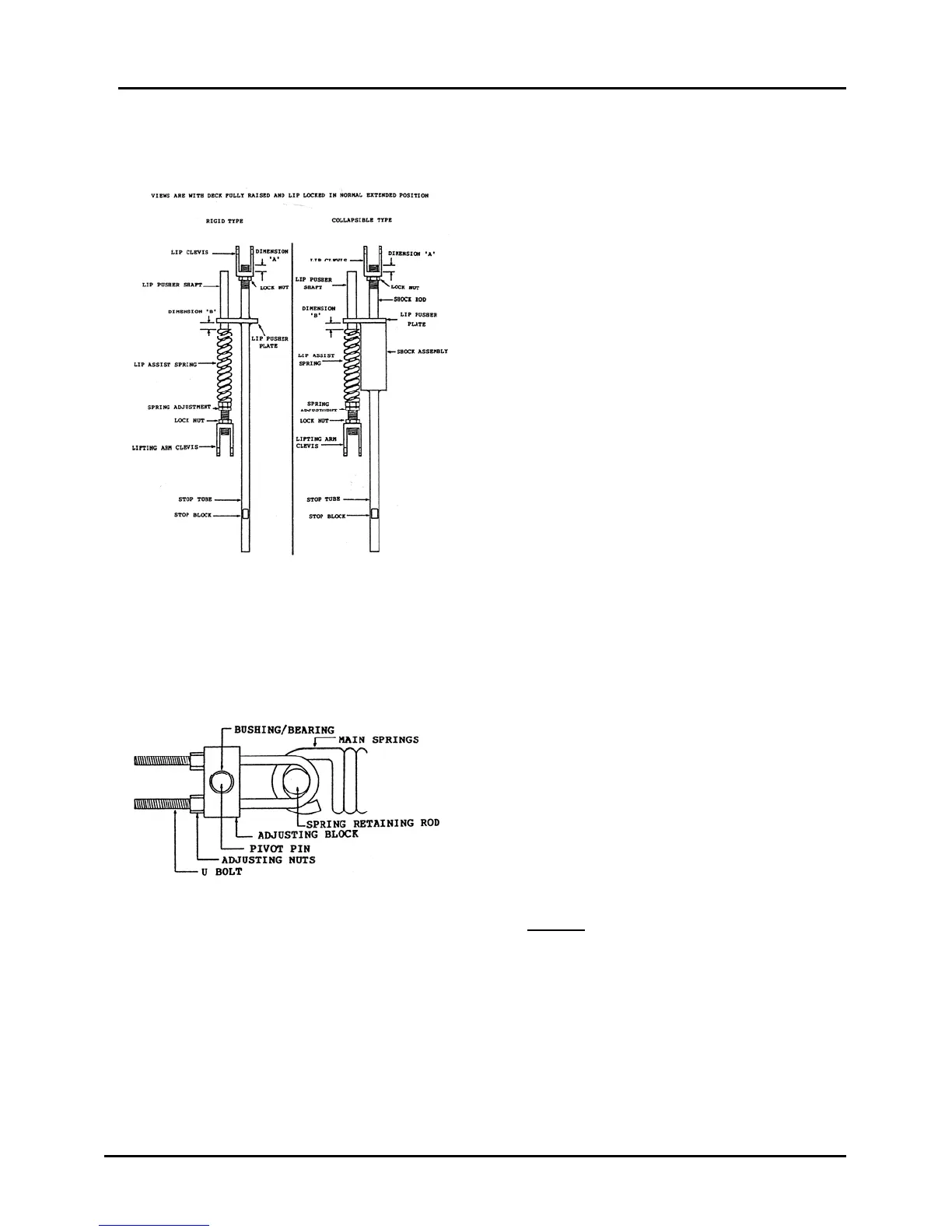
LIP ACTUATOR REPLACEMENT – Cont’d
9) Remove the lip clevis and lock nut
from the old assembly and install onto
the new shock assembly to the
dimension recorded as Dimension 'A',
Figure 40. Do not tighten the lock nut
at this time.
10) In reverse order of removal, install the
Lip Actuator, Lip Pusher Shaft c/w
Assist Spring, Lifting Arm, Lip Lock
Spring and Main Lift Springs.
Replace any components that appear
worn or damaged.
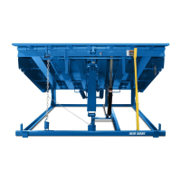
11) Apply tension to the main springs by
turning the 'U' bolt adjusting nuts
clockwise. Maintain equal tension on
each adjusting nut by making four full
turns on each of the four nuts and then
repeating. Continue until all four nuts
are located to produce the dimensions
recorded in Step 3. See Figure 41.
This is an initial adjustment only.
NOTE: To prevent a twisting force on
the lifting arm, each adjusting nut must
be positioned so that the distance
measured from the face of the
adjusting nut to the end of its thread is
equal on all four.
Figure 40
Figure 41