THE
AUTOMATIC TRANSMISSION
Fa
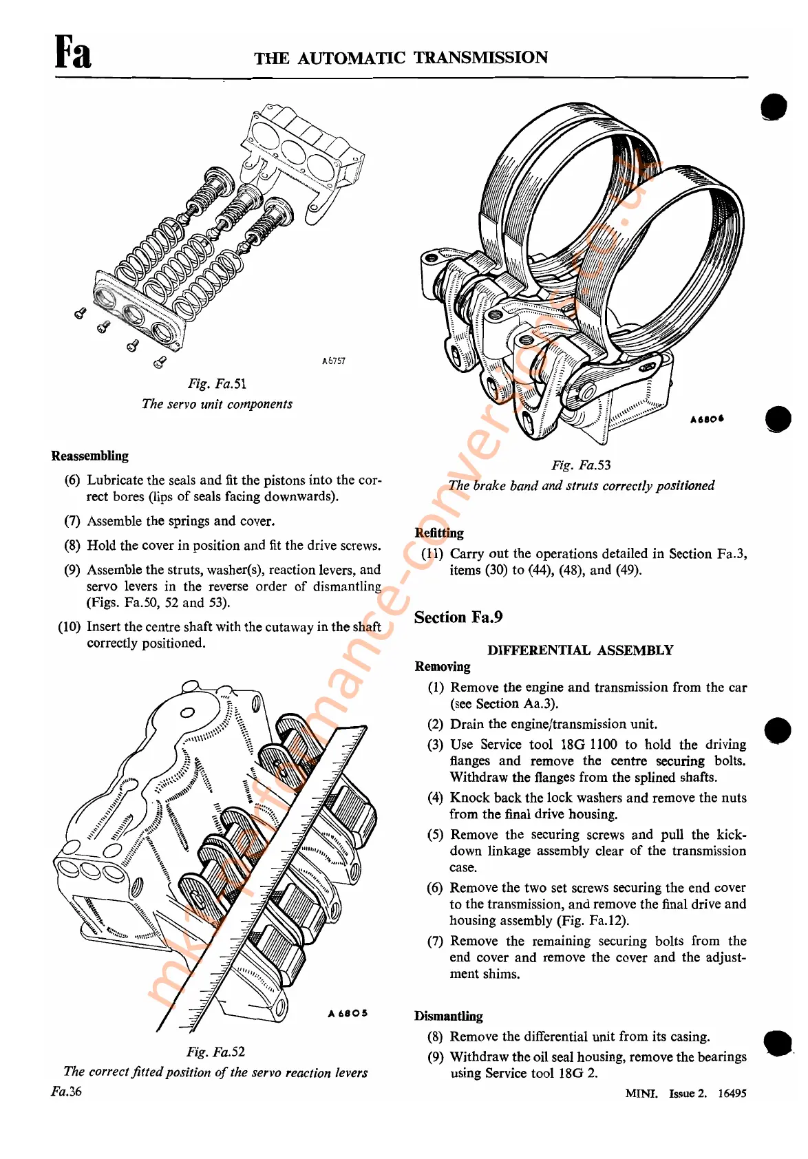
Fig. Fa.51
The servo unit components
Reassembling
(6)
Lubricate the seals
and
fit the pistons into the cor-
rect bores (lips
of
seals facing downwards).
(7) Assemble the springs
and
cover.
(8) Hold the cover in position and fit the drive screws.
(9) Assemble the struts, washer(s), reaction levers, and
servo levers in the reverse order
of
dismantling
(Figs. Fa.50,
52
and
53).
(10) Insert the centre shaft with the cutaway in the shaft
correctly positioned.
Fig. Fa.53
The brake band and struts correctly positioned
Refitting
(11) Carry out the operations detailed in Section Fa.3,
items (30) to (44), (48), and (49).
Section Fa.9
DIFFERENTIAL ASSEMBLY
•
•
Fig. Fa.52
The correct
fitted
position
of
the servo reaction levers
Fa.36
Removing
(1) Remove the engine
and
transmission from the car
(see Section Aa.3).
(2)
Drain the engine/transmission unit. •
(3) Use Service tool
180
1100 to hold the driving .
flanges
and
remove the centre securing bolts.
Withdraw the flanges from the splined shafts.
(4) Knock back the lock washers
and
remove the nuts
from the final drive housing.
(5) Remove the securing screws
and
pull the kick-
down linkage assembly clear
of
the transmission
case.
(6) Remove the two set screws securing the end cover
to the transmission, and remove the final drive
and
housing assembly (Fig. Fa.12).
(7)
Remove the remaining securing bolts from the
end cover and remove the cover
and
the adjust-
ment shims.
Dismantling
«8
9
»W
R~mhodve
thehdi~elrentliahl
u~t
from its
cahsin
b
g
·.
•.
It raw t e 01 sea ousmg, remove t e eanngs
using Service tool
180
2.
MINI.
Issue 2.
16495
mk1-performance-conversions.co.uk



 To Next Page