•
THE
AUTOMATIC TRANSMISSION
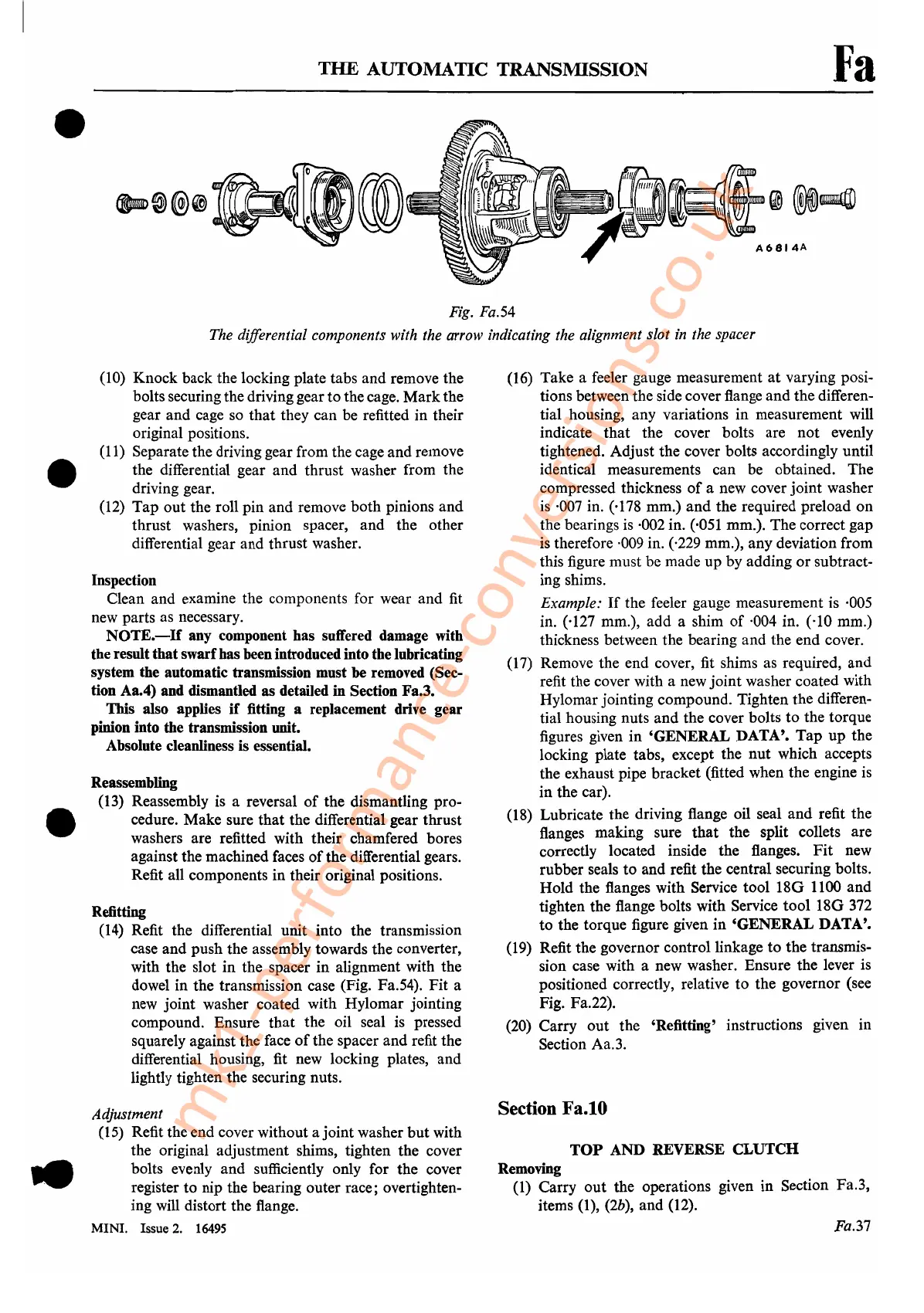
Fig. Fa.54
The differential components with the arrow indicating the alignment slot
in
the spacer
Fa
•
•
(10) Knock back the locking plate tabs and remove the
bolts securing the driving gear to the cage.
Mark
the
gear and cage so
that
they can be refitted in their
original positions.
(11) Separate the driving gear from the cage and remove
the differential gear
and
thrust washer from the
driving gear.
(12)
Tap
out the roll pin and remove both pinions
and
thrust washers, pinion spacer,
and
the other
differential gear and thrust washer.
Inspection
Clean and examine the components for wear and fit
new parts as necessary.
NOTE.-If
any component has suffered damage with
the result thatswarfhas been introduced into the lubricating
system the automatic transmission must
be removed (Sec-
tion Aa.4) and dismantled as detailed in Section Fa.3.
This also applies
if
fitting a replacement drive gear
pinion into the transmission unit.
Absolute cleanliness is essential.
Reassembling
(13) Reassembly is a reversal
of
the dismantling pro-
cedure. Make sure
that
the differential gear thrust
washers are refitted with their chamfered bores
against the machined faces
of
the differential gears.
Refit all components in their original positions.
Refitting
(14) Refit the differential unit into the transmission
case
and
push the assembly towards the converter,
with the slot in the spacer
in
alignment with the
dowel in the transmission case (Fig. Fa.54).
Fit
a
new joint washer coated with Hylomar jointing
compound. Ensure
that
the oil seal is pressed
squarely against the face
of
the spacer and refit the
differential housing, fit new locking plates, and
lightly tighten the securing nuts.
Adjustment
(15) Refit the end cover without a joint washer
but
with
the original adjustment shims, tighten the cover
bolts evenly
and
sufficiently only for the cover
register
to
nip the bearing outer race; overtighten-
ing will distort the flange.
MINI. Issue
2.
16495
(16) Take a feeler gauge measurement
at
varying posi-
tions between the side cover flange and the differen-
tial housing, any variations in measurement will
indicate
that
the cover bolts are
not
evenly
tightened. Adjust the cover bolts accordingly until
identical measurements can be obtained. The
compressed thickness
of
a new cover
joint
washer
is ·007 in. (·178 mm.)
and
the required preload
on
the bearings is ·002 in. ('051 mm.). The correct gap
is therefore ·009 in. (,229 mm.), any deviation from
this figure must be made
up
by adding
or
subtract-
ing shims.
Example:
If
the feeler gauge measurement is ·005
in. ('127 mm.),
add
a shim
of
·004 in. ('10 mm.)
thickness between the bearing and the end cover.
(17) Remove the end cover, fit shims as required,
and
refit the cover with a new
joint
washer coated with
Hylomar jointing compound. Tighten the differen-
tial housing nuts
and
the cover bolts
to
the torque
figures given in 'GENERAL DATA'.
Tap
up
the
locking plate tabs, except the
nut
which accepts
the exhaust pipe bracket (fitted when the engine is
in the car).
(18) Lubricate the driving flange oil seal
and
refit the
flanges making sure
that
the split collets are
correctly located inside the flanges.
Fit
new
rubber seals
to
and
refit the central securing bolts.
Hold the flanges with Service tool
180
1100
and
tighten the flange bolts with Service
tool
18G 372
to
the torque figure given
in
'GENERAL
DATA'.
(19) Refit the governor control linkage
to
the.transmis-
sion case with a new washer. Ensure the lever is
positioned correctly, relative
to
the governor (see
Fig. Fa.22).
(20) Carry
out
the 'Refitting' instructions given in
Section Aa.3.
Section Fa.tO
TOP
AND REVERSE
CLUTCH
Removing
(1) Carry
out
the operations given in Section Fa.3,
items
(1), (2b), and (12).
Fa.37
mk1-performance-conversions.co.uk



 To Next Page