THE FUEL SYSTEM
D
A.9300
Valves
(3)
Run the pump for about
10
minutes and turn off
the
fuel
tap.
If
the pump beats within
12
seconds,
the inlet valve
is
not seating correctly.
PrImIng
(2)
The pump should prime from dry in
10
to
15
seconds and the paraffin (kerosene) should rise in
the glass container until it runs from the overflow
drain pipe.
If
the level does not rise above the small
hole in the drain pipe, the pump
is
faulty. Initial
air bubbles should cease after a minute or two;
if
they do not, there
is
an
air leak on the suction side.
(1) Fit the
SP
adaptor set to a test rig, and a cut-away
cap to the pump. Comiect the pump to a 12-volt
battery with a voltmeter and resistance in circuit.
FUEL
PUMP
TESTING
Section D.S
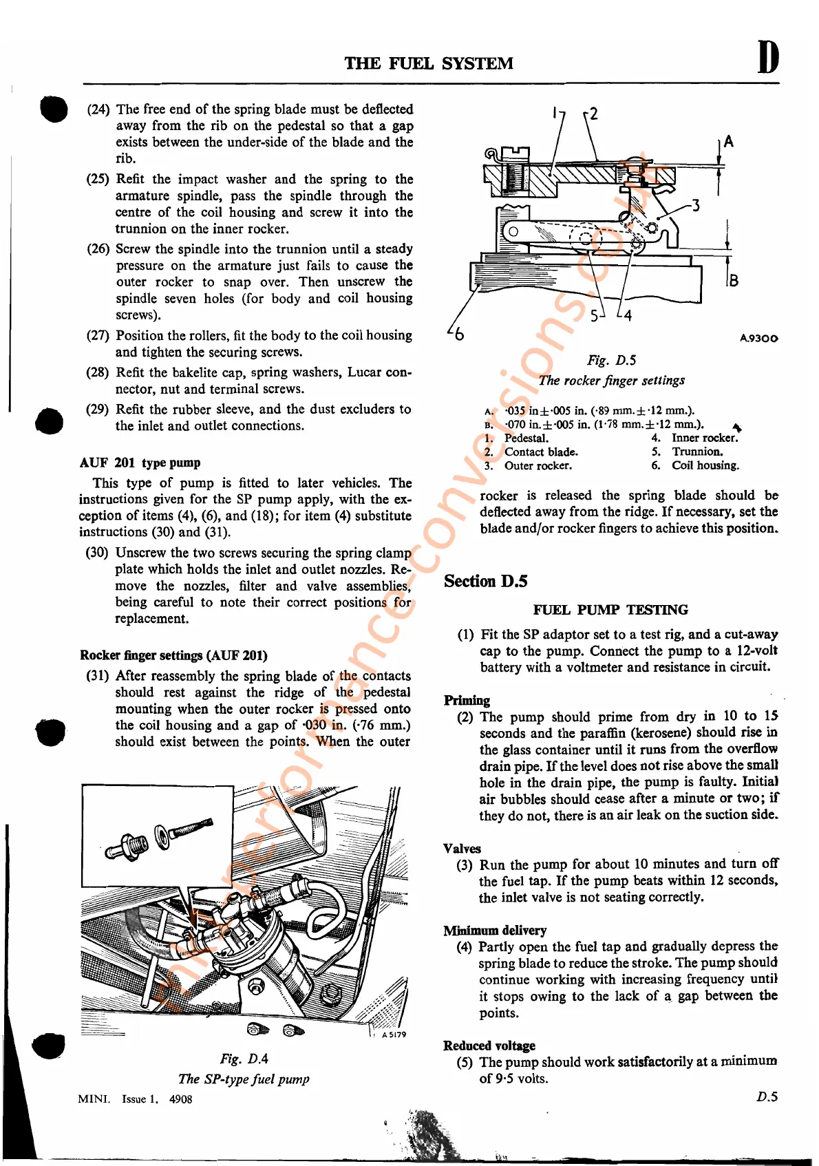
rocker
is
released the spring blade should be
deflected away from the ridge.
If
necessary, set the
blade and/or rocker fingers to achieve this position.
A. '035 in±·OO5 in. ('89
mm.±
'12 mm.).
B. ·070 in.±·OO5 in. (1'78
mm.±·12
mm.). ""
1.
Pedestal. 4. Inner rocker.
2.
Contact blade.
5.
Trunnion.
3. Outer rocker. 6. Coil housing.
Fig. D.S
The rocker finger settings
D.S
Minimum delivery
(4)
Partly open the fuel tap and gradually depress the
spring blade to reduce the stroke. The pump should
continue working with increasing frequency until
it stops owing to the lack
of
~>
gap between the
points.
Reduced voltage
(5)
The pump should work satisfactorily
at
a minimum
of
9·5
volts.
Rocker finger settings (AUF 201)
(31)
After reassembly the spring blade
of
the contacts
should rest against the ridge
of
the pedestal
mounting when the outer rocker
is
pressed onto
the coil housing and a gap
of
'030 in. ('76 mm.)
should exist between the points. When the outer
(24)
The
free
end
of
the spring blade must be deflected
away from the rib on the pedestal so that a gap
exists between the under-side
of
the blade and the
rib.
(25)
Refit the impact washer and the spring to the
armature spindle, pass the spindle through the
centre of the coil housing and screw it into the
trunnion on the inner rocker.
(26)
Screw
the spindle into the trunnion until a steady
pressure on the armature just fails to cause the
outer rocker to snap over. Then unscrew the
spindle seven holes (for body and coil housing
screws).
(27)
Position the rollers,
fit
the body to the coil housing
and tighten the securing screws.
(28)
Refit the bakelite cap, spring washers, Lucar con-
nector, nut and terminal screws.
(29)
Refit the rubber
sleeve,
and the dust excluders to
the inlet and outlet connections.
AUF
201 type pump
This type
of
pump
is
fitted to later vehicles. The
instructions given for the
SP
pump apply, with the
ex-
ception
of
items
(4),
(6),
and (18); for item
(4)
substitute
instructions
(30)
and
(31).
(30)
Unscrew the two screws securing the spring clamp
plate which holds the inlet and outlet nozzles. Re-
move the nozzles, filter and valve assemblies,
being careful to note their correct positions for
replacement.
Fig. D.4
The SP-type
fuel
pump
MINI. Issue
1.
4908
•
•
•
•
mk1-performance-conversions.co.uk