F
THE
TRANSMISSION
A
•
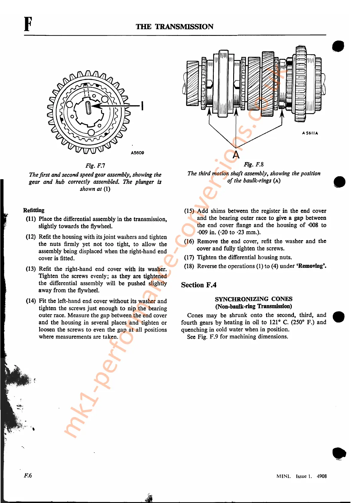
Fig. F.7
The first and second speedgear assembly, showing the
gear and hub correctly assembled. The plunger is
shown
at
(1)
Refitting
(11) Place the differential assembly in the transmission,
slightly towards the
flywheel.
(12)
Refit the housing with its joint washers and tighten
the nuts firmly yet not too tight, to allow the
assembly being displaced when the right-hand end
cover is fitted.
(13)
Refit the right-hand end cover with its washer.
Tighten the screws evenly; as they are tightened
the differential assembly
will
be pushed slightly
away from the
flywheel.
(14)
Fit the left-hand end cover without its washer and
tighten the screws just enough
to
nip the bearing
outer race. Measure the gap between the end cover
and the housing in several places and tighten or
loosen the screws to even the gap at all positions
. where measurements are taken.
Fig. F.8
The third motion shaft assembly, showing the position
of
the baulk-rings
(A)
•
(15)
Add shims between the register in the end cover
and the bearing outer race to give a gap between
the end cover flange and the housing
of
·008
to
·009 in. (·20 to
·23
mm.).
(16)
Remove the end cover, refit the washer and the
cover and fully tighten the screws.
(17) Tighten the differential housing nuts.
(18)
Reverse the operations
(1)
to
(4)
under 'Removing'.
Section F.4
SYNCHRONIZING CONES
(Non-baulk-ring Transmission)
Cones may be shrunk onto the second, third, and •
fourth gears by heating in oil
to
121
0
C. (250° F.) and
....
quenching in cold water when in position.
See
Fig. F.9 for machining dimensions.
•
MINI. Issue
1.
4908
mk1-performance-conversions.co.uk