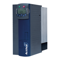
Probus DP V1 Agile 1506/2010
Commissioning via the Operator Panel
6.2 Select the Protocol
• Select Profibus.
Display
Select the "Setup" menu using the arrow keys.
Using the arrow keys select:
Setting up a Communication Interface (Bus Configuration)
Select a protocol using the arrow keys:
CANopen
6.3 Set the Communication Parameters
Parameter Display
391 Node Number
4
The selection is only possible if an optional CM-PDPV1 Communication Module is installed.
Profibus
7 Profibus
This document describes the possibilities and characteristics of the Profibus DP communication module
CM-PDPV1 for the device series Agile.
For the Profibus-DP connection, the frequency inverter must be equipped with the Profibus-
communication module CM-PDPV1. The Profibus component CM-
PDPV1 is enclosed with the inverter
as a separate part and must be fitted by the user.
Note: These instructions are not to be understood as fundamental information on Profibus-
They presuppose underlying knowledge of the methods and modes of effect of Profibus-
DP on the part of the user.
In some sections, setting and display possibilities are described, alterna
Operator Panel, via the VPlus PC-Software. Operation of a PC with the VPlus PC-Software
on the frequency inverter with use of the Profibus component CM-
via an optional interface adapter.
The Profibus component CM-PDPV1 has the ident number 0x0B2C
(hexadecimal). The device's
data set file has the designation BV__0B2C.GSD
. The identification number and designation of the
GSD file were assigned by the Profibus User Organization in Karlsruhe, Germany.
Attention! With the help of the Profibus-DP communication module CM-
access ALL parameters of th
e frequency inverter from the external control unit. Control
of the access via the Control Level (Pa
rameter 28) as with the Operator Panel or the
VPlus PC-S
oftware does not exist. A change of parameters with an unknown meaning to
user can lead to the inoperability of the frequency inverter.

 Loading...


